Integrated Circuit Systems ICS307
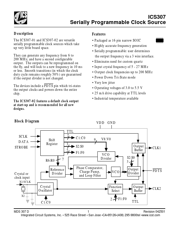
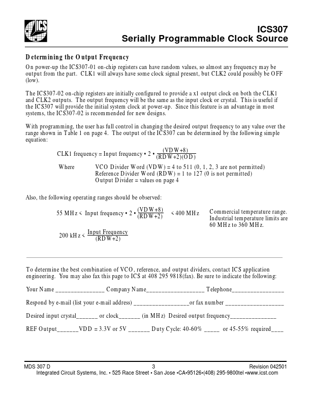
the ICS307 will provide the initial system clock at power-up. With programming, the user has full control in changing the desired output frequency to any value over the range shown in Table 1 on page 4. The output of the ICS307 can be determined by the following simple equation: (VDW+8) CLK1 frequency = Input frequency • 2 • (RDW+2)(OD) Where VCO Divider Word (VDW) = 4 to 511 (0, 1, 2, 3 are not permitted) Reference Divider Word (RDW) = 1 to 127 (0 is not permitted) Output Divider = values on page 4 Also, the following operating ranges should be observed: (VDW+8) 55 MHz < Input frequency • 2 • (RDW+2) 200 kHz < Input Frequency (RDW+2) < 400 MHz Commercial temperature range.| Part No. | ICS307 |
|---|---|
| Datasheet | ICS307 Download |
| Manufacturer |  Integrated Circuit Systems |
| Description | Serially Programmable Clock Source |
| Buy | Stock & Price |