IDT74ALVCH16345
IDT74ALVCH16345 is 3.3V CMOS REGISTERED ADDRESS LINE DRIVER manufactured by Integrated Device Technology.
IDT74ALVCH16345 3.3V CMOS REGISTERED ADDRESS LINE DRIVER WITH 3-STATE OUTPUTS
INDUSTRIAL TEMPERATURE RANGE
3.3V CMOS REGISTERED ADDRESS LINE DRIVER WITH 3-STATE OUTPUTS AND BUS-HOLD
- 0.5 MICRON CMOS Technology
- Typical t SK(o) (Output Skew) < 250ps
- ESD > 2000V per MIL-STD-883, Method 3015; > 200V using machine model (C = 200p F, R = 0)
- VCC = 3.3V ± 0.3V, Normal Range
- VCC = 2.7V to 3.6V, Extended Range ..
- VCC = 2.5V ± 0.2V
- CMOS power levels (0.4µ W typ. static)
- Rail-to-Rail output swing for increased noise margin
- Available in TSSOP package
Features
:
DESCRIPTION:
DRIVE Features
:
- High Output Drivers: ±24m A
- Suitable for heavy loads
APPLICATIONS:
- -
- -
3.3V high speed systems 3.3V and lower voltage puting systems High speed synchronous DRAM modules PC motherboards
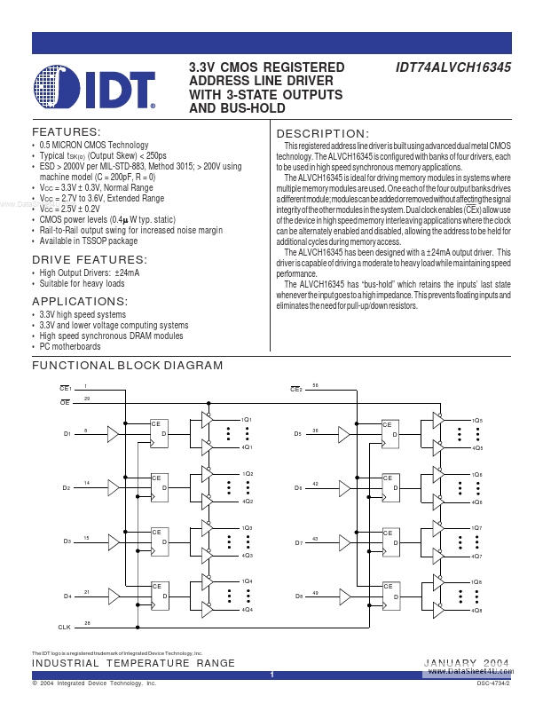
This registered address line driver is built using advanced dual metal CMOS technology. The ALVCH16345 is configured with banks of four drivers, each to be used in high speed synchronous memory applications. The ALVCH16345 is ideal for driving memory modules in systems where multiple memory modules are used. One each of the four output banks drives a different module; modules can be added or removed without affecting the signal integrity of the other modules in the system. Dual clock enables (CEx) allow use of the device in high speed memory interleaving applications where the clock can be alternately enabled and disabled, allowing the address to be held for additional cycles during memory access. The ALVCH16345 has been designed with a ±24m A output driver. This driver is capable of driving a moderate to heavy load while maintaining speed performance. The ALVCH16345 has “bus-hold” which retains the inputs’ last state whenever the input goes to a high impedance. This prevents floating inputs and eliminates the need for pull-up/down resistors.
FUNCTIONAL BLOCK DIAGRAM
CE 1 OE
1 29
CE 2
CE D1
1Q...