Intel 8742AH
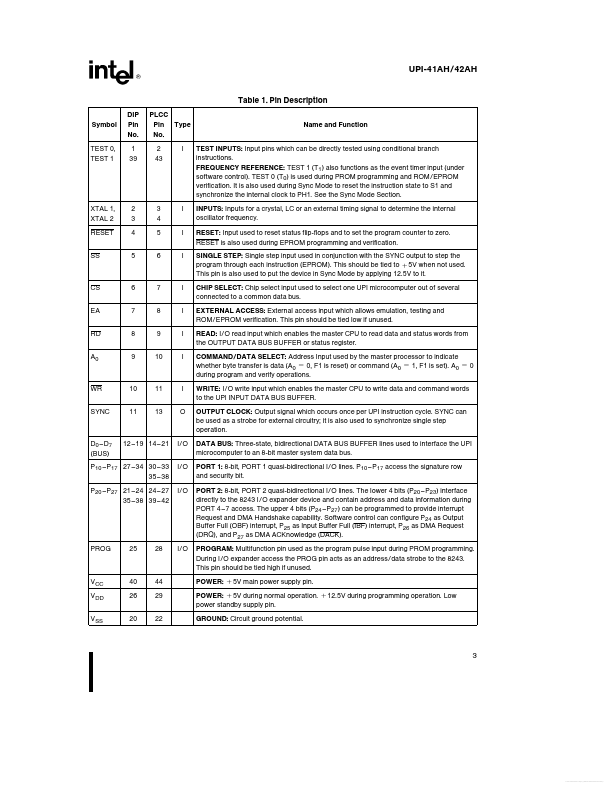
This should be tied to a 5V when not used This pin is also used to put the device in Sync Mode by applying 12 5V to it CHIP SELECT Chip select input used to select one UPI microcomputer out of several connected to a common data bus EXTERNAL ACCESS External access input which allows emulation testing and ROM EPROM verification This pin should be tied low if unused READ I O read input which enables the master CPU to read data and status words from the OUTPUT DATA BUS BUFFER or status register COMMAND DATA| Part No. | 8742AH |
|---|---|
| Datasheet | 8742AH Download |
| Manufacturer |  Intel |
| Description | Universal Peripheral Interface 8-Bit Slave Microcontroller |
| Buy | Stock & Price |
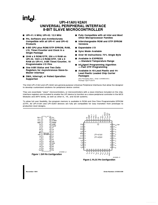
DESCRIPTION
Symbol DIP Pin No 1 39 PLCC Pin Type No 2 43 I Name and Function TEST 0 TEST 1 TEST INPUTS Input pins which can be directly tested using conditional branch instructions FREQUENCY REFERENCE TEST 1 (T1) also functions as the event timer input (under software control) TEST 0 (T0) is used during PROM programming and ROM EPROM verification It is also used during Sync Mode to reset the instruction state to S1 and synchronize the internal clock to PH1 See the Sync Mode Section INPUTS Inputs for a crystal LC or an external timing signal to determine the internal oscillator frequency RESET Input used to reset status flip-flops and to set the program counter to zero RESET is also used during EPROM programming and verification SINGLE STEP Single step input used in conjunction with the SYNC output to step the program through each instruction (EPROM)