IR21381Q
IR21381Q is 3-PHASE AC MOTOR CONTROLLER IC manufactured by International Rectifier.
- Part of the IR22381QPBF comparator family.
- Part of the IR22381QPBF comparator family.
Features
- -
- -
- -
- -
- -
- - Floating channel up to +600V or +1200V “soft” over-current shutdown turns off desaturated output Integrated desaturation circuit Active biasing on sensing desaturation input Two stage turn on output for di/dt control Integrated brake IGBT driver with protection Voltage feedback sensing function Separate pull-up/pull-down output drive pins Matched delay outputs Under voltage lockout with hysteresis band Programmable deadtime Hard shutdown function
Product Summary
VOFFSET (max) IO +/- (min.) VOUT Brake (IO +/- min.)
Deadtime Asymmetry Skew (max.) Deadtime (typ. with RDT=39KΩ) DESAT Blanking time (typ.) DESAT filter time (typ.) Active bias on Desat input pin DSH, DSL input voltage threshold (typ.) Soft shutdown duration time (typ.) Voltage feedback matching delay time (max.) 600V or 1200V 220m A / 460m A 12.5V-20V 40m A/80m A 125nsec 1µsec 4.5µsec 3.0µsec 90Ω 8.0V 6.0µsec 400nsec
Description
The IR22381Q and IR21381Q are high voltage, 3-phase IGBT driver best suited for AC motor drive applications. Integrated desaturation logic provides all mode of overcurrent protection, including ground fault protection. The sensing desaturation input is provided by active bias stage to reject noise. Soft shutdown is predominantly initiated in the event of overcurrent followed by turnoff of all six outputs. A shutdown input is provided for a customized shutdown function. The DT pin allows external resistor to program the deadtime. Output drivers have separate turn on/off pins with two stage turn-on output to achieve the desired di/dt switching level of IGBT. Voltage feedback provides accurate volt x second measurement.
Package
64-Lead MQFP w/o 13 leads
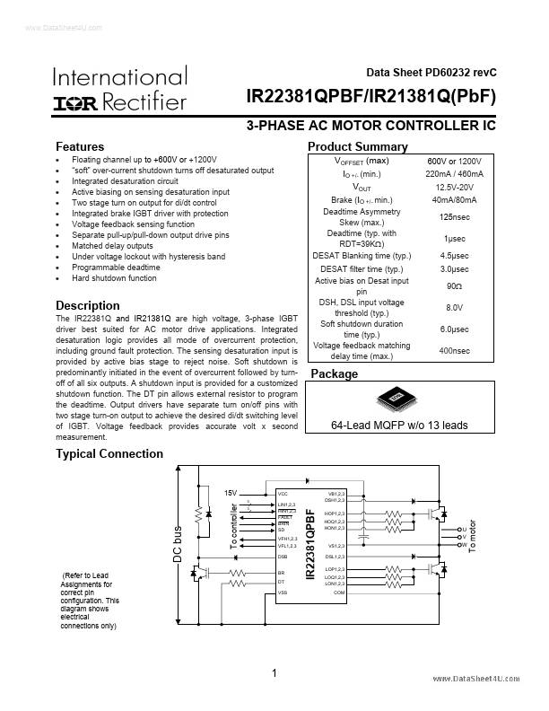
Typical Connection
15V
To controller
IR22381QPBF
DC bus
VFH1,2,3 VFL1,2,3 DSB
VS1,2,3 DSL1,2,3 LOP1,2,3 LOQ1,2,3 LON1,2,3
(Refer to Lead Assignments for correct pin configuration. This diagram shows electrical connections only)
BR DT VSS
To motor
LIN1,2,3 HIN1,2,3 FAULT...