IRFB4115GPbF
Overview
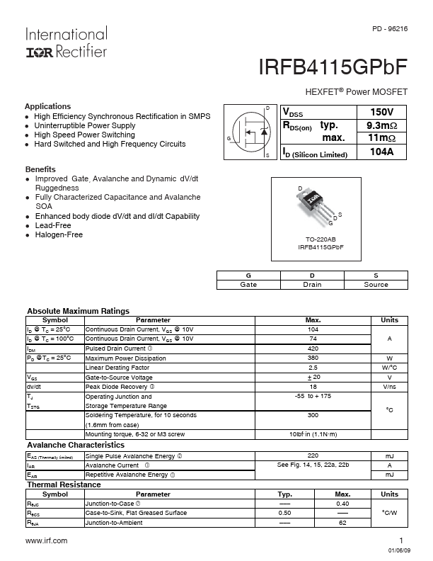
PD - 96216 Applications l High Efficiency Synchronous Rectification in SMPS l Uninterruptible Power Supply l High Speed Power Switching l Hard Switched and High Frequency Circuits G Benefits l Impr...
| Part | IRFB4115GPbF |
|---|---|
| Description | Power MOSFET |
| Category | MOSFET |
| Manufacturer | International Rectifier |
| Size | 309.56 KB |
PD - 96216 Applications l High Efficiency Synchronous Rectification in SMPS l Uninterruptible Power Supply l High Speed Power Switching l Hard Switched and High Frequency Circuits G Benefits l Impr...
| Part Number | Manufacturer | Description |
|---|---|---|
| IRFB4115G | Inchange Semiconductor | N-Channel MOSFET |
| IRFB4115 | Inchange Semiconductor | N-Channel MOSFET |
| IRFB4110 | Inchange Semiconductor | N-Channel MOSFET Transistor |
| IRFB4110G | Inchange Semiconductor | N-Channel MOSFET |