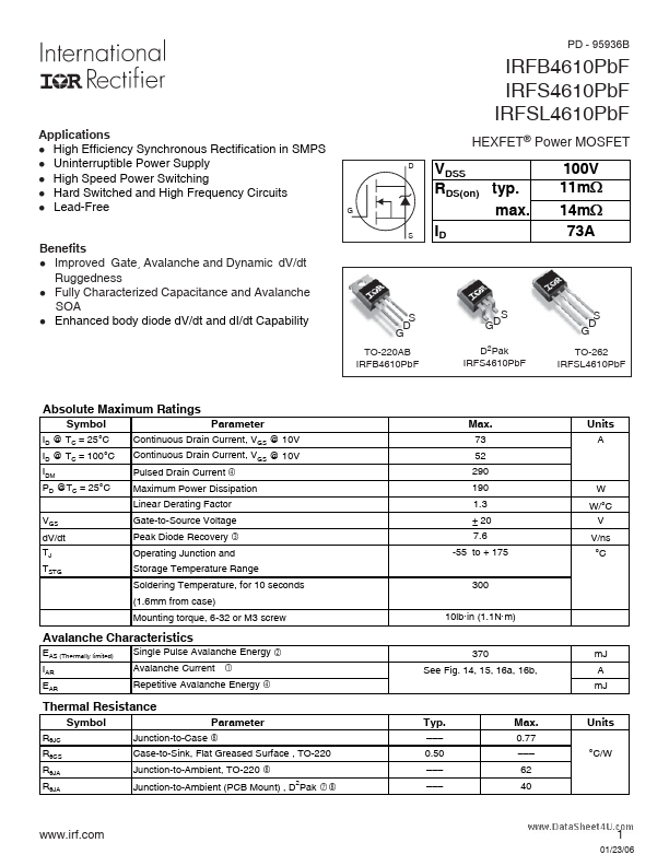
Datasheet4U Logo Datasheet4U.com

IRFB4610PBF - HEXFET Power MOSFET

Datasheet Summary

Features

  • d breakdown voltage (1.3 factor accounts for voltage increase during avalanche). 6. Iav = Allowable avalanche current. 7. ∆T = Allowable rise in junction temperature, not to exceed Tjmax (assumed as 25°C in Figure 14, 15). tav = Average time in avalanche. D = Duty cycle in avalanche = tav.
  • f ZthJC(D, tav) = Transient thermal resistance, see Figures 13) PD (ave) = 1/2 ( 1.3.
  • BV.
  • Iav) = DT/ ZthJC Iav = 2DT/ [1.3.
  • BV.
  • Zth] EAS (AR) = PD (ave).
  • tav Starting TJ , Junction Temperat.

📥 Download Datasheet

Datasheet preview – IRFB4610PBF
Other Datasheets by International Rectifier

Full PDF Text Transcription

Click to expand full text
PD - 95936B IRFB4610PbF IRFS4610PbF IRFSL4610PbF Applications l High Efficiency Synchronous Rectification in SMPS l Uninterruptible Power Supply l High Speed Power Switching l Hard Switched and High Frequency Circuits l Lead-Free Benefits l Improved Gate, Avalanche and Dynamic dV/dt Ruggedness l Fully Characterized Capacitance and Avalanche SOA l Enhanced body diode dV/dt and dI/dt Capability HEXFET® Power MOSFET D G S VDSS RDS(on) typ. max. ID 100V 11m: 14m: 73A S D G TO-220AB IRFB4610PbF S GD D2Pak IRFS4610PbF S D G TO-262 IRFSL4610PbF Absolute Maximum Ratings Symbol ID @ TC = 25°C ID @ TC = 100°C IDM PD @TC = 25°C VGS dV/dt TJ TSTG Parameter Continuous Drain Current, VGS @ 10V Continuous Drain Current, VGS @ 10V Pulsed Drain Current Max. 73 52 290 190 1.3 ± 20 7.
Published: |