Datasheet4U Logo Datasheet4U.com

IRFR13N15D - Power MOSFET

Key Features

  • N15D/IRFU13N15D I-Pak (TO-251AA) Package Outline Dimensions are shown in millimeters (inches) 6 .7 3 (.26 5 ) 6 .3 5 (.25 0 ) -A 5 .4 6 (.2 1 5 ) 5 .2 1 (.2 0 5 ) 4 1 .2 7 ( .0 5 0 ) 0 .8 8 ( .0 3 5 ) 2 .3 8 (.0 9 4 ) 2 .1 9 (.0 8 6 ) 0 .5 8 (.0 2 3 ) 0 .4 6 (.0 1 8 ) L E A D A S S IG N M E N T S 1 - GATE 2 - D R A IN 3 - SOURCE 4 - D R A IN 6 .4 5 (.2 4 5 ) 5 .6 8 (.2 2 4 ) 1 .5 2 (.0 6 0 ) 1 .1 5 (.0 4 5 ) 1 -B 2.2 8 (.0 9 0) 1.9 1 (.0 7 5) 9 .6 5 ( .3 8 0 ) 8 .8 9 ( .3 5 0 ) 2 3 6 .2 2 (.

📥 Download Datasheet

Full PDF Text Transcription (Reference)

The following content is an automatically extracted verbatim text from the original manufacturer datasheet and is provided for reference purposes only.

View original datasheet text
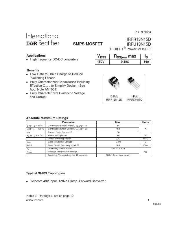
PD - 93905A SMPS MOSFET Applications High frequency DC-DC converters IRFR13N15D IRFU13N15D HEXFET® Power MOSFET l VDSS 150V RDS(on) max 0.18Ω ID 14A Benefits l Low Gate-to-Drain Charge to Reduce Switching Losses l Fully Characterized Capacitance Including Effective COSS to Simplify Design, (See App. Note AN1001) l Fully Characterized Avalanche Voltage and Current D-Pak IRFR13N15D I-Pak IRFU13N15D Absolute Maximum Ratings Parameter ID @ TC = 25°C ID @ TC = 100°C IDM PD @TC = 25°C VGS dv/dt TJ TSTG Continuous Drain Current, VGS @ 10V Continuous Drain Current, VGS @ 10V Pulsed Drain Current  Power Dissipation Linear Derating Factor Gate-to-Source Voltage Peak Diode Recovery dv/dt ƒ Operating Junction and Storage Temperature Range Soldering Temperature, for 10 seconds Max. 14 9.