Datasheet4U Logo Datasheet4U.com

IRFR3806PbF - Power MOSFET

Features

  • on temperature, not to exceed Tjmax (assumed as 20 25°C in Figure 14, 15). tav = Average time in avalanche. D = Duty cycle in avalanche = tav.
  • f ZthJC(D, tav) = Transient thermal resistance, see Figures 13) 0 25 50 75 100 125 150 175 Starting TJ , Junction Temperature (°C) PD (ave) = 1/2 ( 1.3.
  • BV.
  • Iav) = DT/ ZthJC Iav = 2DT/ [1.3.
  • BV.
  • Zth] EAS (AR) = PD (ave).
  • tav Fig 15. Maximum Avalanche Energy vs. Temperature www. irf. com 5 IRR (A) VGS(th) , Gate threshold Voltag.

📥 Download Datasheet

Other Datasheets by International Rectifier

Full PDF Text Transcription

Click to expand full text
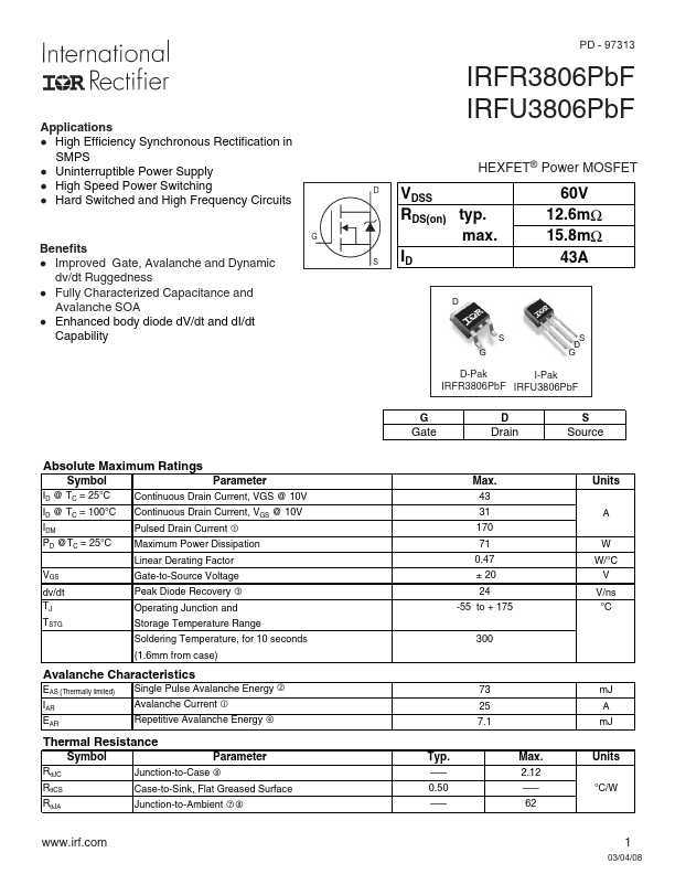
Applications l High Efficiency Synchronous Rectification in SMPS l Uninterruptible Power Supply l High Speed Power Switching l Hard Switched and High Frequency Circuits Benefits l Improved Gate, Avalanche and Dynamic dv/dt Ruggedness l Fully Characterized Capacitance and Avalanche SOA l Enhanced body diode dV/dt and dI/dt Capability G Absolute Maximum Ratings Symbol Parameter ID @ TC = 25°C Continuous Drain Current, VGS @ 10V ID @ TC = 100°C IDM PD @TC = 25°C Continuous Drain Current, VGS @ 10V Pulsed Drain Current c Maximum Power Dissipation Linear Derating Factor VGS Gate-to-Source Voltage dv/dt Peak Diode Recovery e TJ TSTG Operating Junction and Storage Temperature Range Soldering Temperature, for 10 seconds (1.
Published: |