Datasheet Summary
Applications l High Efficiency Synchronous Rectification in SMPS l Uninterruptible Power Supply l High Speed Power Switching l Hard Switched and High Frequency Circuits
Benefits l Improved Gate, Avalanche and Dynamic dV/dt
Ruggedness l Fully Characterized Capacitance and Avalanche
SOA l Enhanced body diode dV/dt and dI/dt Capability l Lead-Free
- 96186A
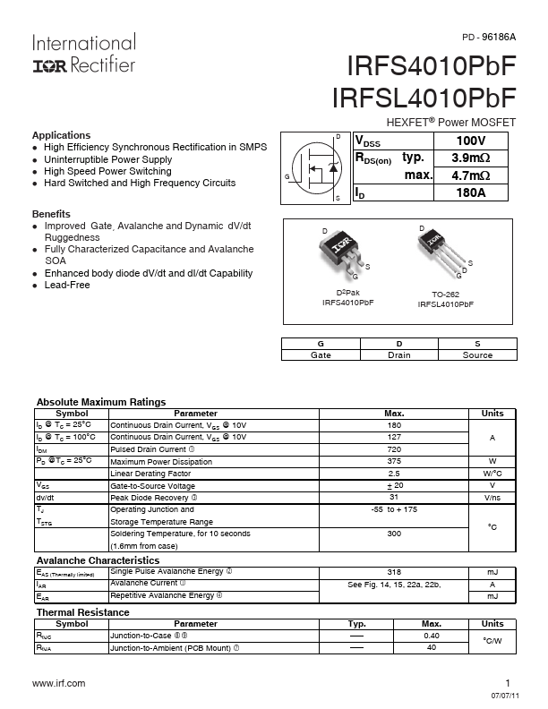
IRFSL4010PbF
HEXFET® Power MOSFET
D VDSS RDS(on) typ. max.
100V
3.9m: 4.7m:
S ID
180A
D2Pak IRFS4010PbF
TO-262 IRFSL4010PbF
G Gate
D Drain
S...