IRFS4115PbF
Overview
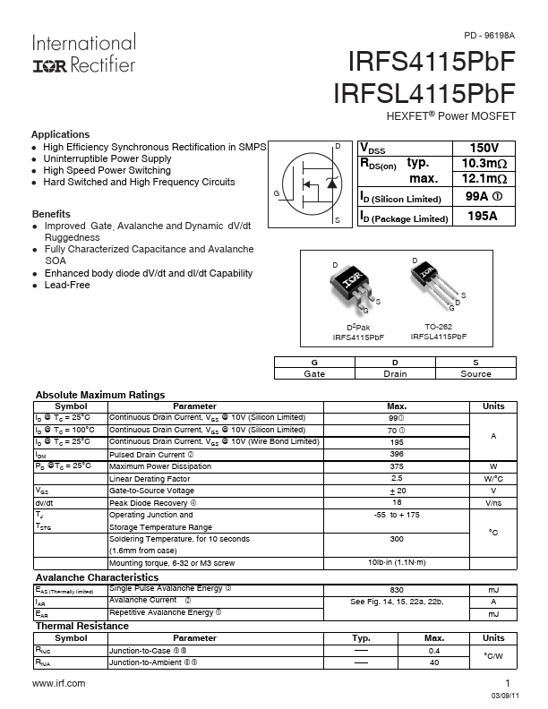
Applications l High Efficiency Synchronous Rectification in SMPS l Uninterruptible Power Supply l High Speed Power Switching l Hard Switched and High Frequency Circuits G Benefits l Improved Gate, Ava...
| Part | IRFS4115PbF |
|---|---|
| Description | Power MOSFET |
| Category | MOSFET |
| Manufacturer | International Rectifier |
| Size | 299.58 KB |
Applications l High Efficiency Synchronous Rectification in SMPS l Uninterruptible Power Supply l High Speed Power Switching l Hard Switched and High Frequency Circuits G Benefits l Improved Gate, Ava...
| Part Number | Manufacturer | Description |
|---|---|---|
| IRFS4115PbF | Inchange Semiconductor | N-Channel MOSFET |