Datasheet4U Logo Datasheet4U.com

IRFS4510PbF - Power MOSFET

Key Features

  • lowable avalanche current. 7. ΔT = Allowable rise in junction temperature, not to exceed Tjmax (assumed as 25°C in Figure 14, 15). tav = Average time in avalanche. D = Duty cycle in avalanche = tav.
  • f ZthJC(D, tav) = Transient thermal resistance, see Figures 13) PD (ave) = 1/2 ( 1.3.
  • BV.
  • Iav) = DT/ ZthJC Iav = 2DT/ [1.3.
  • BV.
  • Zth] EAS (AR) = PD (ave).
  • tav Fig 15. Maximum Avalanche Energy vs. Temperature www. irf. com 5 VGS(th), Gate threshold Voltage (V) IRFS/SL4510PbF 4.5 4.

📥 Download Datasheet

Full PDF Text Transcription (Reference)

The following content is an automatically extracted verbatim text from the original manufacturer datasheet and is provided for reference purposes only.

View original datasheet text
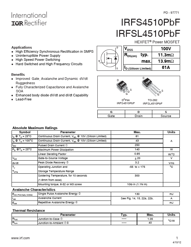
Applications l High Efficiency Synchronous Rectification in SMPS l Uninterruptible Power Supply l High Speed Power Switching l Hard Switched and High Frequency Circuits G Benefits l Improved Gate, Avalanche and Dynamic dV/dt Ruggedness l Fully Characterized Capacitance and Avalanche SOA l Enhanced body diode dV/dt and dI/dt Capability l Lead-Free PD - 97771 IRFS4510PbF IRFSL4510PbF HEXFET® Power MOSFET D VDSS 100V RDS(on) typ. 11.3mΩ max. 13.