IRL40S212
IRL40S212 is Power MOSFET manufactured by International Rectifier.
Application
- Brushed Motor drive applications
- BLDC Motor drive applications
- Battery powered circuits
- Half-bridge and full-bridge topologies
- Synchronous rectifier applications
- Resonant mode power supplies
- OR-ing and redundant power switches
- DC/DC and AC/DC converters
- DC/AC Inverters
D
Benefits
- Optimized for Logic Level Drive
- Improved Gate, Avalanche and Dynamic d V/dt Ruggedness
- Fully Characterized Capacitance and Avalanche SOA
- Enhanced body diode d V/dt and d I/dt Capability
- Lead-Free
- Ro HS pliant, Halogen-Free
G Gate
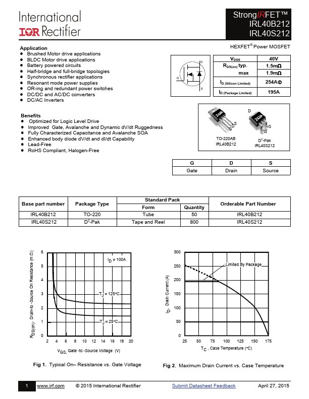
Strong IRFET™ IRL40B212 IRL40S212
HEXFET® Power MOSFET
VDSS RDS(on) typ. max
ID (Silicon Limited)
ID (Package Limited)
40V 1.5m 1.9m
254A
195A
TO-220AB IRL40B212
S G D2-Pak IRL40S212
D Drain
S Source
Base part number
IRL40B212 IRL40S212
Package Type
TO-220 D2-Pak
Standard...