IRS2110SPBF
Features
HIGH AND LOW SIDE DRIVER
- Floating channel designed for bootstrap operation Product Summary
- Fully operational to +500 V or +600 V
- Tolerant to negative transient voltage, d V/dt immune
- Gate drive supply range from 10 V to 20 V
VOFFSET (IRS2110) (IRS2113)
500 V max. 600 V max.
- Undervoltage lockout for both channels
IO+/-
2 A/2 A
- 3.3 V logic patible
- Separate logic supply range from 3.3 V to 20 V
VOUT
10 V
- 20 V
- Logic and power ground ± 5V offset ton/off (typ.)
130 ns & 120 ns
- CMOS Schmitt-triggered inputs with pull-down
- Cycle by cycle edge-triggered shutdown logic
- Matched propagation delay for both channels
- Outputs in phase with inputs
Delay Matching (IRS2110) 10 ns max. (IRS2113) 20 ns max.
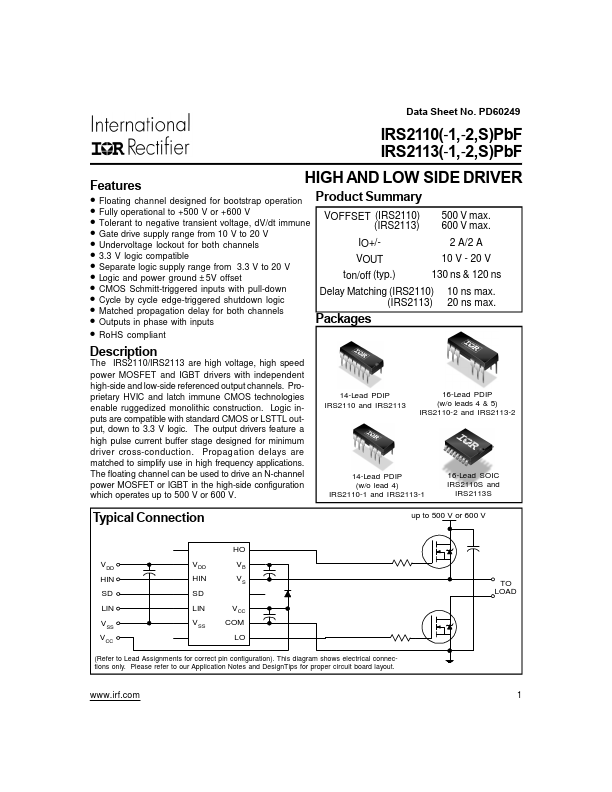
Packages
- Ro HS pliant
Description
The IRS2110/IRS2113 are high voltage, high speed power MOSFET and IGBT drivers with independent high-side and...