Datasheet Summary
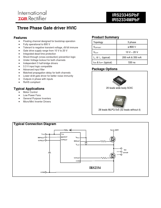
Three Phase Gate driver HVIC
Features
- Floating channel designed for bootstrap operation
- Fully operational to 600 V
- Tolerant to negative transient voltage, dV/dt immune
- Gate drive supply range from 10 V to 20 V
- Integrated dead time protection
- Shoot-through (cross-conduction) prevention logic
- Under-Voltage lockout for both channels
- Independent 3 half-bridge drivers
- 3.3 V input logic patible
- Advanced input filter
- Matched propagation delay for both channels
- Lower di/dt gate driver for better noise immunity
- Outputs in phase with inputs
- RoHS pliant
Typical Applications
- Motor Control
- Low Power Fans
- General Purpose Inverters
- Micro/Mini Inverter...