IRS2453D
IRS2453D is FULL-BRIDGE DRIVER manufactured by International Rectifier.
IRS2453(1)D(S)
Product Summary
Topology VOFFSET Io+ & I o- (typical) Deadtime (typical) Full-bridge 600 V 180 m A & 260 m A 1.0 μs (IRS2453D) 0.5 μs (IRS24531D)
Features
- -
- -
- -
- -
- -
- - Integrated 600 V full-bridge gate driver CT, RT programmable oscillator 15.6 V Zener clamp on VCC Micropower startup Logic level latched shutdown pin Non-latched shutdown on CT pin (1/6th VCC) Internal bootstrap FETs Excellent latch immunity on all inputs & outputs ESD protection on all pins 14-lead SOIC or PDIP package 0.5 or 1.0μs (typ.) internal dead time Ro HS pliant
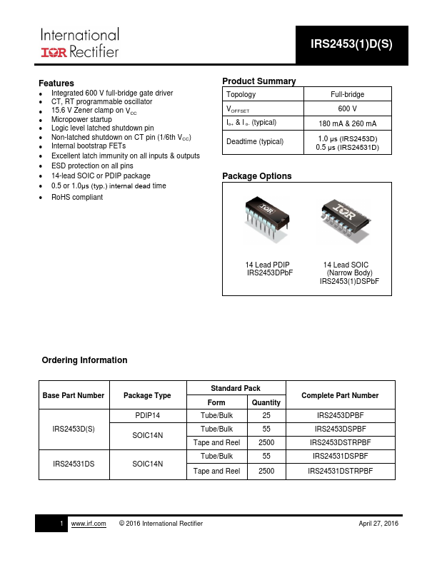
Package Options
14 Lead PDIP IRS2453DPb F
14 Lead SOIC (Narrow Body) IRS2453(1)DSPb F
Ordering Information
Standard Pack Base Part Number Package Type Form PDIP14 IRS2453D(S) SOIC14N Tape and Reel Tube/Bulk IRS24531DS SOIC14N Tape and Reel 2500 IRS24531DSTRPBF 2500 55 IRS2453DSTRPBF IRS24531DSPBF Tube/Bulk Tube/Bulk Quantity 25 55 IRS2453DPBF IRS2453DSPBF plete Part Number
.irf.
© 2012 International Rectifier
November 28, 2012 http://..
IRS2453(1)D(S)
Table of Contents
Ordering Information Description Typical Connection Diagram Qualification Information...