Datasheet4U Logo Datasheet4U.com

ISL22426 - Dual Digitally Controlled Potentiometer

General Description

TSSOP PIN 1 2 3 4 5 6 7 8 9 10 11 12 13 14 SYMBOL VCC SHDN RH0 RL0 RW0 NC SCK SDO GND RW1 RL1 RH1 CS SDI SPI interface clock input Open drain SPI interface Data Output Device ground pin “Wiper” terminal of DCP1 “Low” terminal of DCP1 “High” terminal of DCP1 Chip Select active low input SPI interfac

Key Features

  • Two potentiometers in one package.
  • 128 resistor taps.
  • SPI serial interface.
  • Non-volatile storage of wiper position.
  • Wiper resistance: 70Ω typical @ 3.3V.
  • Shutdown mode.
  • Shutdown current 5µA max.
  • Power supply: 2.7V to 5.5V.
  • 50kΩ or 10kΩ total resistance.
  • High reliability - Endurance: 1,000,000 data changes per bit per register - Register data retention: 50 years @ T.

📥 Download Datasheet

Full PDF Text Transcription (Reference)

The following content is an automatically extracted verbatim text from the original manufacturer datasheet and is provided for reference purposes only.

View original datasheet text
® ISL22426 Dual Digitally Controlled Potentiometer (XDCP™) Data Sheet July 17, 2006 FN6180.0 
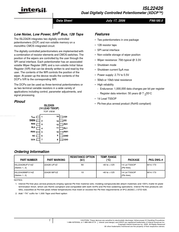
Low Noise, Low Power, SPI® Bus, 128 Taps The ISL22426 integrates two digitally controlled potentiometers (DCP) and non-volatile memory on a monolithic CMOS integrated circuit. The digitally controlled potentiometers are implemented with a combination of resistor elements and CMOS switches. The position of the wipers are controlled by the user through the SPI serial interface. Each potentiometer has an associated volatile Wiper Register (WR) and a non-volatile Initial Value Register (IVR) that can be directly written to and read by the user. The contents of the WR controls the position of the wiper. At power-up the device recalls the contents of the DCP’s IVR to the corresponding WR.