Datasheet4U Logo Datasheet4U.com

X9269 - Dual Digitally-Controlled Potentiometers

General Description

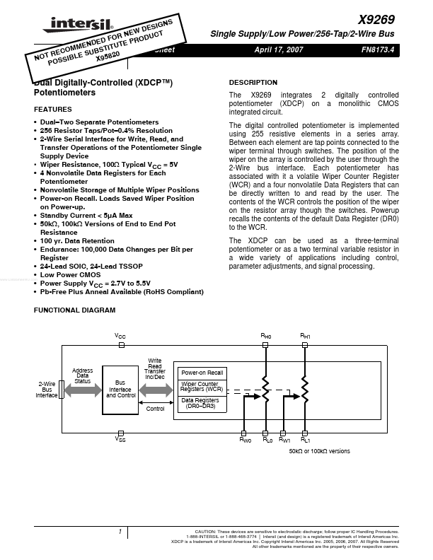
The X9269 integrates 2 digitally controlled potentiometer (XDCP) on a monolithic CMOS integrated circuit.

The digital controlled potentiometer is implemented using 255 resistive elements in a series array.

Between each element are tap points connected to the wiper terminal through switches.

Key Features

  • Dual.
  • Two Separate Potentiometers.
  • 256 Resistor Taps/Pot.
  • 0.4% Resolution.
  • 2-Wire Serial Interface for Write, Read, and Transfer Operations of the Potentiometer Single Supply Device.
  • Wiper Resistance, 100Ω Typical VCC = 5V.
  • 4 Nonvolatile Data Registers for Each Potentiometer.
  • Nonvolatile Storage of Multiple Wiper Positions.
  • Power-on Recall. Loads Saved Wiper Position on Power-up.
  • Standby Current < 5µA Max.

📥 Download Datasheet

Full PDF Text Transcription (Reference)

The following content is an automatically extracted verbatim text from the original manufacturer datasheet and is provided for reference purposes only.

View original datasheet text
NS ESIG D N EW CT F O R PR O D U D E E ND UT E Data Sheet O M M U B S TI T C E S R 0 9582 NOT SSIBLE X PO ® X9269 Single Supply/Low Power/256-Tap/2-Wire Bus April 17, 2007 FN8173.4 Dual Digitally-Controlled (XDCP™) Potentiometers FEATURES • Dual–Two Separate Potentiometers • 256 Resistor Taps/Pot–0.4% Resolution • 2-Wire Serial Interface for Write, Read, and Transfer Operations of the Potentiometer Single Supply Device • Wiper Resistance, 100Ω Typical VCC = 5V • 4 Nonvolatile Data Registers for Each Potentiometer • Nonvolatile Storage of Multiple Wiper Positions • Power-on Recall. Loads Saved Wiper Position on Power-up. • Standby Current < 5µA Max • 50kΩ, 100kΩ Versions of End to End Pot Resistance • 100 yr.