Datasheet4U Logo Datasheet4U.com

X9410 - Dual Digitally Controlled Potentiometer

Datasheet Summary

Description

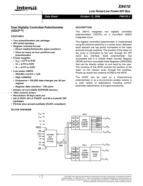
The X9410 integrates two digitally controlled potentiometers (XDCPs) on a monolithic CMOS integrated circuit.

The digitally controlled potentiometer is implemented using 63 resistive elements in a series array.

Between each element are tap points connected to the wiper terminal through switches.

Features

  • Two potentiometers per package.
  • SPI serial interface.
  • Register oriented format - Direct read/write/transfer wiper positions - Store as many as four positions per potentiometer.
  • Power supplies - VCC = 2.7V to 5.5V - V+ = 2.7V to 5.5V - V- = -2.7V to -5.5V.
  • Low power CMOS - Standby current < 1µA - High reliability - Endurance - 100,000 data changes per bit per register - Register data retention - 100 years.
  • 8-bytes of nonvolatile EEPROM memory.

📥 Download Datasheet

Datasheet preview – X9410

Datasheet Details

Part number X9410
Manufacturer Intersil Corporation
File Size 423.63 KB
Description Dual Digitally Controlled Potentiometer
Datasheet download datasheet X9410 Datasheet
Additional preview pages of the X9410 datasheet.
Other Datasheets by Intersil Corporation

Full PDF Text Transcription

Click to expand full text
® X9410 Low Noise/Low Power/SPI Bus Data Sheet October 12, 2006 FN8193.2 Dual Digitally Controlled Potentiometer (XDCP™) FEATURES • Two potentiometers per package • SPI serial interface • Register oriented format - Direct read/write/transfer wiper positions - Store as many as four positions per potentiometer • Power supplies - VCC = 2.7V to 5.5V - V+ = 2.7V to 5.5V - V- = -2.7V to -5.5V • Low power CMOS - Standby current < 1µA - High reliability - Endurance - 100,000 data changes per bit per register - Register data retention - 100 years • 8-bytes of nonvolatile EEPROM memory www.DataSheet4U.
Published: |