DESCRIPTION
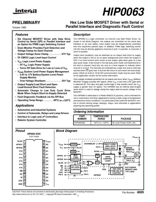
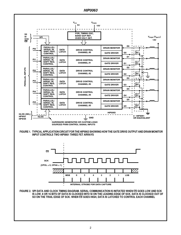
As shown in the Block Diagram, the outputs are controlled via the serial data interface or, by user option, each output may be independently controlled from the respective parallel input. In addition, PWM logic switching control (HLOS) may be directly applied to channels 0 and 1 in parallel, or channels 4 and 5 in parallel. Output fault conditions may be detected as an output load short to supply when the output is ON or as an open load/ground short when the output is OFF. If an over-current short exists at one output, gate drive goes to a low duty cycle mode. It will remain in the low duty cycle mode until switched off or the fault is cleared. Fault bits are sent to a fault register to indicate which channel is at fault. The fault bits are indicated by a logic one and is internally latched when CS goes low. A fault bit will return to zero when the fault disappears. Either an 8-bit or 16-bit SPI communication mode may be used. Refer to the application section for bit control information. Intersil