Intersil X9261
The X9261 integrates 2 digitally controlled potentiometer (XDCP) on a monolithic CMOS integrated circuit. The digital controlled potentiometer is implemented using 255 resistive elements in a series array. The position of the wiper on the array is controlled by the user through the SPI bus interface.| Part No. | X9261 |
|---|---|
| Datasheet | X9261 Download |
| Manufacturer |  Intersil |
| Description | Dual Digitally-Controlled Potentiometers |
| Buy | Stock & Price |
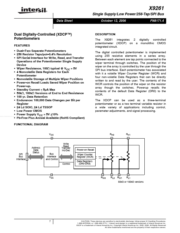
FEATURES
● Dual–Two Separate Potentiometers● 256 Resistor Taps/pot–0.4% Resolution
● SPI Serial Interface for Write, Read, and Transfer Operations of the Potentiometer Single Supply Device
● Wiper Resistance, 100Ω typical @ VCC = 5V
● 4 Nonvolatile Data Registers for Each Potentiometer
● Nonvolatile Storage of Multiple Wiper Positions
● Power-on Recall Loads Saved Wiper Position on Power-up.
● Standby Current < 5µA Max
● 50kΩ, 100kΩ Versions of End to End Resistance
● 100 yr. Data Retention
● Endurance: 100,000 Data Changes per Bit per Register
● 24 Ld SOIC, 24 Ld TSSOP
● Low Power CMOS
● Power Supply VCC = 5V ±10%
● Pb-Free Plus Anneal Available (RoHS Compliant) FUNCTIONAL DIAGRAM VCC
DESCRIPTION
Between each element are tap points connected to the wiper terminal through switches. Each potentiometer has associated with it a volatile Wiper Counter Register (WCR) and four non-volatile Data Registers that can be directly written to and read by the user. The contents of the WCR controls the position of the wiper on the resistor array though the switches.
