Intersil X9410
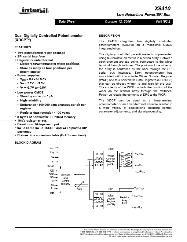
The X9410 integrates two digitally controlled potentiometers (XDCPs) on a monolithic CMOS integrated circuit. The digitally controlled potentiometer is implemented using 63 resistive elements in a series array. The position of the wiper on the array is controlled by the user through the SPI serial bus interface.| Part No. | X9410 |
|---|---|
| Datasheet | X9410 Download |
| Manufacturer |  Intersil |
| Description | Dual Digitally Controlled Potentiometer |
| Buy | Stock & Price |
FEATURES
● Two potentiometers per package● SPI serial interface
● Register oriented format - Direct read/write/transfer wiper positions - Store as many as four positions per potentiometer
● Power supplies - VCC = 2.7V to 5.5V - V+ = 2.7V to 5.5V - V- = -2.7V to -5.5V
● Low power CMOS - Standby current < 1µA - High reliability - Endurance - 100,000 data changes per bit per register - Register data retention - 100 years
● 8-bytes of nonvolatile EEPROM memory
● 10kΩ resistor arrays
● Resolution: 64 taps each pot
● 24 Ld SOIC, 24 Ld TSSOP, and 24 Ld plastic DIP packages
● Pb-free plus anneal available (RoHS compliant) BLOCK DIAGRAM VCC VSS V+ VHOLD CS SCK SO SI A0 A1 WP
DESCRIPTION
Between each element are tap points connected to the wiper terminal through switches. Each potentiometer has associated with it a volatile Wiper Counter Register (WCR) and four nonvolatile Data Registers (DR0:DR3) that can be directly written to and read by the user. The contents of the WCR controls the position of the wiper on the resistor array through the switches.
