1N5393
Key Features
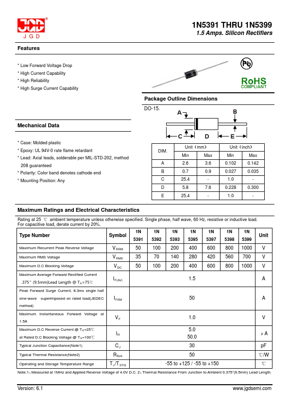
- 1N5391 THRU 1N5399 1.5 Amps
| Part Number | Manufacturer | Description |
|---|---|---|
| 1N5393G | Dc Components | TECHNICAL SPECIFICATIONS OF GLASS PASSIVATED RECTIFIER |
| 1N5393GP | Micro Commercial Components | 1.5 Amp Glass Passivated Rectifier |
| 1N5393G | HY | GLASS PASSIVATED RECTIFIERS |
| 1N5393 | MIC | AXIAL SILASTIC GUARD JUNCTION STANDARD RECTIFIER |
| 1N5393 | EIC Semiconductor | SILICON RECTIFIER DIODES |
| 1N5393 | Vishay | General Purpose Plastic Rectifier |
| 1N5393GP | FAGOR | 1.5 Amp. Glass Passivated Junction Rectifier |
| 1N5393 | Diotec Semiconductor | Silicon Rectifiers |
| 1N5393G | Diodes Incorporated | 1.5A GLASS PASSIVATED RECTIFIER |
| 1N5393G | EIC Semiconductor | GLASS PASSIVATED JUNCTION SILICON RECTIFIERS |