SR106S Overview
Key Specifications
Mount Type: Surface Mount
Pins: 2
Height: 1.2 mm
Length: 2.05 mm
Key Features
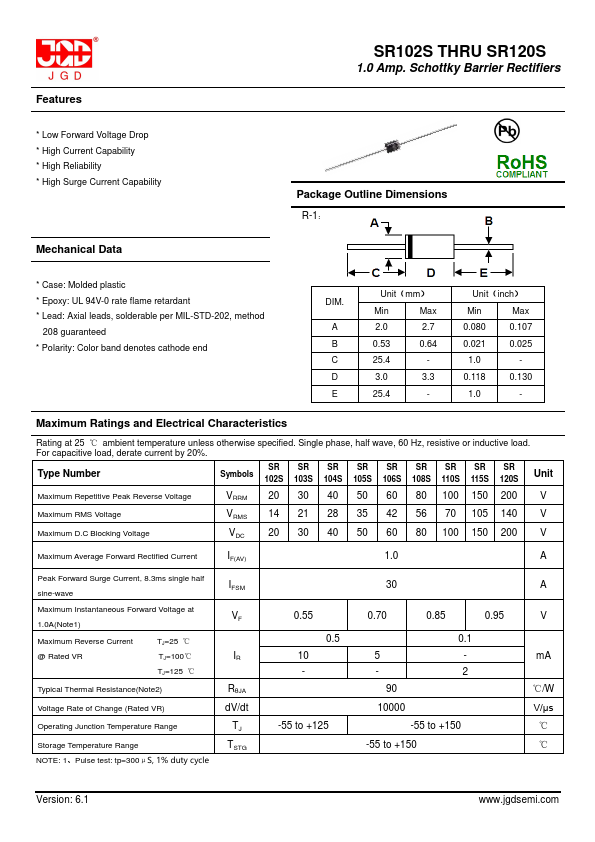
- SR102S THRU SR120S 1.0 Amp
| Part | SR106S |
|---|---|
| Description | 1.0 Amp. Schottky Barrier Rectifiers |
| Manufacturer | JGD |
| Size | 352.31 KB |
Mount Type: Surface Mount
Pins: 2
Height: 1.2 mm
Length: 2.05 mm
| Seller | Inventory | Price Breaks | Buy |
|---|---|---|---|
| DigiKey | 0 | 10000+ : 0.22511 USD | View Offer |
| TME | 0 | 10000+ : 0.158 EUR | View Offer |
| Part Number | Manufacturer | Description |
|---|---|---|
| SR1060 | Formosa MS | 10.0 AMP SCHOTTKY BARRIER RECTIFIERS |
| SR1060CT | GW | 10.0 AMP SCHOTTKY BARRIER RECTIFIERS |
| SR1060 | Rectron | SCHOTTKY BARRIER RECTIFIER |
| SR1060CT | Galaxy Microelectronics | Dual Schottky Rectifiers |
| SR1060 | JINAN JINGHENG | SCHOTTKY BARRIER RECTIFIER |