Datasheet4U.com
🌙
UG4KB100 Datasheet | JGD
Part:
UG4KB100
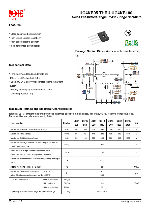
Description:
Glass Passivated Single Phase Bridge Rectifiers
Manufacturer:
JGD
Size:
261.98 KB
UG4KB100 Datasheet (PDF) Download
Related UG4KB100 Datasheets
UG4KB10 Glass Passivated Single Phase Bridge Rectifiers
JGD
UG4KB100
×
Close