KDI DTS-29
TRANSFER SWITCHES
| Part No. | DTS-29 |
|---|---|
| Datasheet | DTS-29 Download |
| Manufacturer | KDI |
| Description | TRANSFER SWITCHES |
| Buy | Stock & Price |
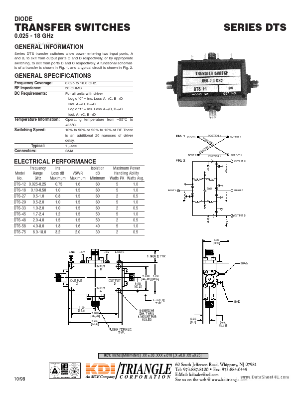
DIODE TRANSFER SWITCHES 0.025 - 18 GHz GENEwRwwA.DLatIaNShFeOet4RUM.coAmTION Series DTS transfer switches allow power entering two input ports, A and B, to exit from output ports C and D respectively, or by appropriate switching, to exit from ports D and C respectively. A functional schematic of a transfer is shown in Fig. 1, and a typical circuit is shown in Fig. 2. GENERAL SPECIFICATIONS Frequency Coverage: RF Impedance: DC Requirements: Temperature Information: Switching Speed: Typical: Connectors: 0.025 to 18.0 GHz. 50 OHMS. For all units with driver Logic “0” = Ins. Loss A→C, B→D Isol. A→D, B→C Logic “1” = Ins. Loss A→D, B→C Isol. A→C, B→D Operating temperature from –55°C to +85°C. 10% to 90% or 90% to 10% of RF. There is an additional 20 nanosec of driver delay. 1
●sec SMA ELECTRICAL PERFORMANCE Frequency Ins Isolation Model Range Loss dB VSWR dB No. GHz Maximum Maximum Minimum DTS-12 0.025-0.25 0.75 1.6 60 DTS-18 0.10-0.50 1.0 1.5 60 DTS-27 0.5-1.0 0.8 1.5 60 DTS-29 0.5-2.0 1.0...
●sec SMA ELECTRICAL PERFORMANCE Frequency Ins Isolation Model Range Loss dB VSWR dB No. GHz Maximum Maximum Minimum DTS-12 0.025-0.25 0.75 1.6 60 DTS-18 0.10-0.50 1.0 1.5 60 DTS-27 0.5-1.0 0.8 1.5 60 DTS-29 0.5-2.0 1.0...