KDG40R12KT3
KDG40R12KT3 is IGBT Module manufactured by KEDA.
IGBT Module
Features
:
- IGBT Inverter Short Circuit Rated 10μs
- IGBT Inverter Low Saturation Voltage
- Low Switching Loss
- Low Stray Inductance
- Lead Free, pliant With Ro HS Requirement
Applications:
- Industrial Inverters
- Servo Applications
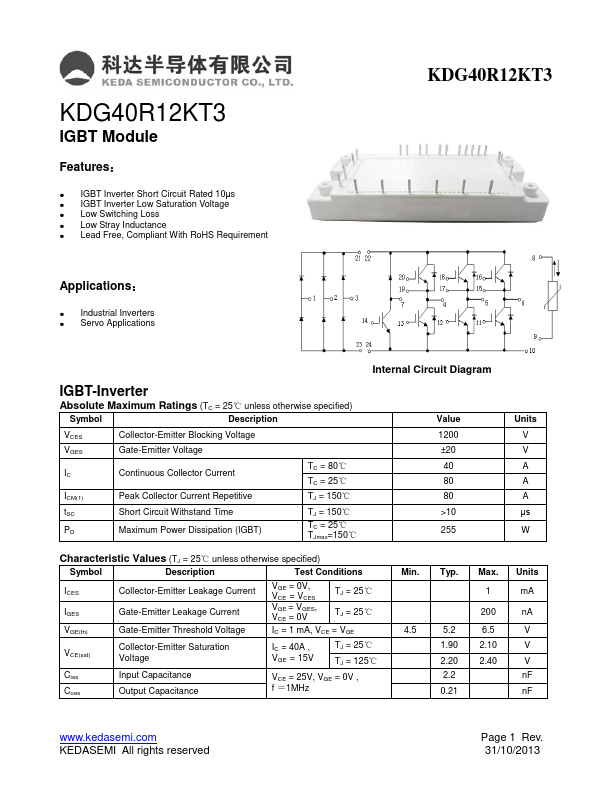
IGBT-Inverter...