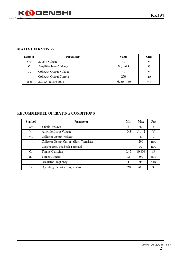
MAXIMUM RATINGS
Symbol VCC VI VO Tstg Supply Voltage Amplifier Input Voltage Collector Output Voltage Collector Output Current Storage Temperature Parameter Value 41 VCC +0.3 41 250 -65 to +150 Unit V V V mA °C RECOMMENDED OPERATING CONDITIONS Symbol VCC VI VO Supply Voltage Amplifier Input Voltage Collector Output Voltage Collector Output Current (Each Transistor) Current Into Feed back Terminal CT RT TA Timing Capacitor Timing Resistor Oscillator Frequency Operating Free-Air Temperature 0.47 1.8 1 -20 Parameter Min 7 -0.3 Max 40 VCC - 2 40 200 0.3 10.000 500 300 +85 Unit V V V mA mA nF KΩ KHz °C 2 KK494 ELECTRICAL CHARACTERISTICS
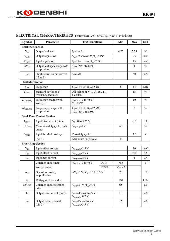
(Temperature -20 ∼ 85°C, VCC = 15 V, f=10 kHz)) Symbol Reference Section Vref Vregin Vregout ∆Vref ISC Output Voltage Output regulation Input regulation Output Voltage change with temperature Short-circuit output current (Note 1) Frequency Standard deviation of frequency (Note 2) Frequency change with voltage Frequency change with temperature IO=1 mA VCC=7 V... Kodenshi AUK Group