FEATURES
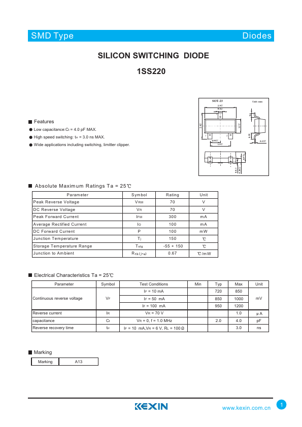
Low capacitance:Ct = 4.0 pF MAX. High speed switching: trr = 3.0 ns MAX. Wide applications including switching, limitter clipper. +0.1 2.4 -0.1 SOT-23 2.9+0.1 -0.1 0.4+0.1 -0.1 3 1 2 0.95+0.1 -0.1 1.9+0.1 -0.1 Absolute Maxim um Ratings Ta = 25 P aram eter Peak Reverse Voltage DC Reverse Voltage Peak Forward Current Average Rectified Current DC Forward Current Junction Tem perature Storage Temperature Range Junction to Am bient Sym bol VRM VR IFM IO P Tj Tstg R Rating 70 70 300 100 100 150 -55 + 150 0.67 Unit V V mA mA mW /m W 0-0.1 +0.1 0.38 -0.1 +0.1 1.3 -0.1 +0.1 0.97 -0.1 0.55 0.4 Unit: mm 0.1+0.05 -0.01 1.Base 2.Emitter 3.collector ELECTRICAL CHARACTERISTICS
Ta = 25 Parameter Symbol Continuous reverse voltage VF Reverse current IR capacitance Ct Reverse recovery time trr Test Conditions IF = 10 mA IF = 50 mA IF = 100 mA VR = 70 V VR = 0, f = 1.0 MHz IF = 10 mA,VR = 6 V, RL = 100 Min Typ Max Unit 720 850 850 1000 mV 950 1200 1.0 A 2.0 4.0 pF 3.0 ns Marking Marking A13 1