FEATURES
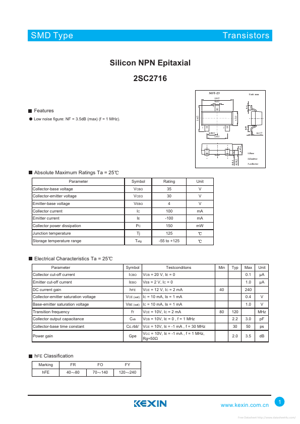
+0.1 2.4-0.1 Low noise figure: NF = 3.5dB (max) (f = 1 MHz). +0.1 1.3-0.1 1 +0.1 0.95-0.1 +0.1 1.9-0.1 2 0.55 0.4 3 +0.05 0.1-0.01 +0.1 0.97-0.1 1.Base 2.Emitter 3.collector ABSOLUTE MAXIMUM RATINGS
Ta = 25 Parameter Collector-base voltage Collector-emitter voltage Emitter-base voltage Collector current Emitter current Collector power dissipation Junction temperature Storage temperature range Symbol VCBO VCEO VEBO IC IE PC Tj Tstg Rating 35 30 4 100 -100 150 125 -55 to +125 Unit V V V mA mA mW ELECTRICAL CHARACTERISTICS
Ta = 25 Parameter Collector cut-off current Emitter cut-off current DC current gain Collector-emitter saturation voltage Base-emitter saturation voltage Transition frequency Collector output capacitance Collector-base time constant Power gain Symbol ICBO IEBO hFE Testconditons VCB = 20 V, IE = 0 VEB = 2 V, IC = 0 VCE = 12 V, IC = 2 mA 40 Min Typ Max 0.1 1.0 240 0.4 1.0 80 120 2.2 30 2.0 3.0 50 3.5 V V MHz pF ps dB Unit ìA ìA VCE (sat) IC = 10 mA, IB = 1 mA VBE...