Kexin Electronics HR1L2Q
Digital Transistors
| Part No. | HR1L2Q |
|---|---|
| Datasheet | HR1L2Q Download |
| Manufacturer | Kexin Electronics |
| Description | Digital Transistors |
| Buy | Stock & Price |
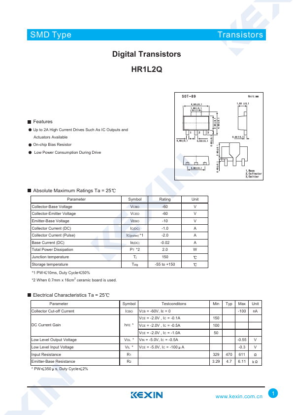
FEATURES
Up to 2A High Current Drives Such As IC Outputs and Actuators Available On-chip Bias Resistor Low Power Consumption During DriveABSOLUTE MAXIMUM RATINGS
Ta = 25 Parameter Collector-Base Voltage Collector-Emitter Voltage Emitter-Base Voltage Collector Current (DC) Collector Current (Pulse) Base Current (DC) Total Power Dissipation Junction temperature Storage temperature *1 PW 10ms, Duty Cycle 50% *2 When 0.7mm x 16cm2 ceramic board is used. Symbol VCBO VCEO VEBO IC(DC) IC(pulse) *1 IB(DC) PT *2 Tj Tstg Rating -60 -60 -10 -1.0 -2.0 -0.02 2.0 150 -55 to +150 Unit V V V A A A WELECTRICAL CHARACTERISTICS
Ta = 25 Parameter Collector Cut-off Current DC Current Gain Low Level Output Voltage Low Level Input Voltage Input Resistance Emitter-Base Resistance * PW 350 s, Duty Cycle 2% Symbol Testconditons ICBO VCB = -60V, IE = 0 VCE = -2.0V , IC = -0.1A hFE * VCE = -2.0V , IC = -0.5A VCE = -2.0V , IC = -1.0A VOL * VIN = -5.0V, IC = -0.5A VIL * VCE = -5.0V, IC = -100 A R1 R2 Min Typ Max...