Datasheet4U Logo Datasheet4U.com

ML145040 - 8-Bit A/D Converters

General Description

DIGITAL INPUTS AND OUTPUTS CS (Pin 15) Active

low chip select input.

state control of Dout.

impedance state.

Key Features

  • a break.
  • before.
  • make switching structure to minimize noise injection into the analog inputs. The source impedance driving these inputs must be ≤ 10 kΩ. NOTE: $B addresses an on.
  • chip test voltage of (Vref + VAG)/2, and produces an output of $80 if the converter is functioning properly. However, a ± 1 LSB deviation from $80 occurs in the presence of sufficient system noise (external to the chip) on VDD, VSS, Vref or VAG. POWER AND.

📥 Download Datasheet

Datasheet Details

Part number ML145040
Manufacturer LANSDALE Semiconductor
File Size 443.58 KB
Description 8-Bit A/D Converters
Datasheet download datasheet ML145040 Datasheet

Full PDF Text Transcription (Reference)

The following content is an automatically extracted verbatim text from the original manufacturer datasheet and is provided for reference purposes only.

View original datasheet text
www.DataSheet4U.com ML145040 ML145041 8-Bit A/D Converters With Serial Interface Silicon-Gate CMOS SEMICONDUCTOR TECHNICAL DATA Legacy Device: Motorola MC145040, MC145041 The ML145040 and ML145041 are low-cost 8-bit A/D Converters with serial interface ports to provide communication with microprocessors and microcomputers. The converters operate from a single power supply with a maximum nonlinearity of ± 1/2 LSB over the full temperature range. No external trimming is required. The ML145040 allows an external clock input (A/D CLK) to operate the dynamic A/D conversion sequence. The ML145041 has an internal clock and an end–of–
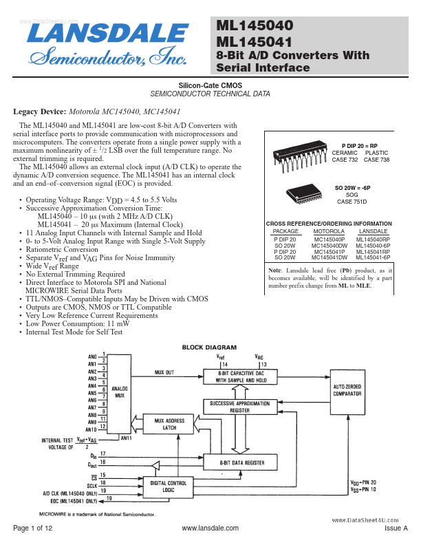
conversion signal (EOC) is provided. • Operating Voltage Range: VDD = 4.5 to 5.