LF205-S Overview
Key Specifications
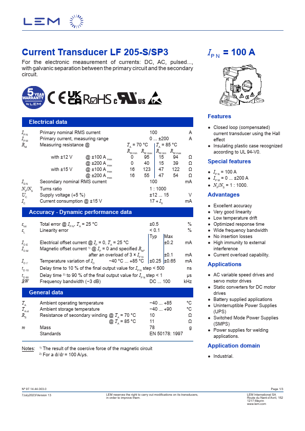
Package: Module
Mount Type: Chassis Mount, Panel, Screw
Operating Voltage: 15 V
Max Operating Temp: 85 °C
Key Features
- Closed loop (compensated) current transducer using the Hall effect
- Insulating plastic case recognized according to UL 94-V0. Special features
- IP N = 100 A
- IP M = 0 ... ±200 A
- Excellent accuracy