FDB107S
Features
Rating to 1000V PRV Surge overload rating to 30 Amperes peak Ideal for printed circuit board Reliable low cost construction utilizing molded plastic technique results in inexpensive product Lead solderable per MIL-STD-202 method 208 Lead: silver plated copper, solderde plated Plastic material has UL flammability classification 94V-O Polarity symbols molded on body Weight: 0.016 ounces,0.45 grams
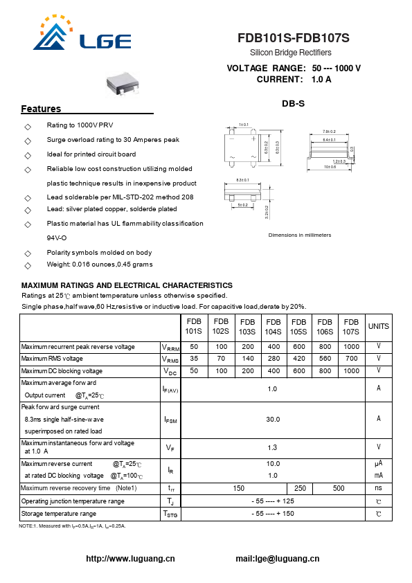
1± 0.1
8.3± 0.1 5± 0.2
6.3± 0.2 8.3± 0.3
DB-S
7.9± 0.2 6.4± 0.1
1.2± 0.3 10± 0.6
3.2± 0.2
Dimensions in millimeters
MAXIMUM RATINGS AND ELECTRICAL CHARACTERISTICS Ratings at 25 ambient temperature unless otherwise specified.
Single phase,half wave,60 Hz,resistive or inductive load. For capacitive load,derate by 20%.
FDB 101S
FDB 102S
FDB FDB FDB 103S 104S 105S
FDB 106S
FDB 107S
UNITS
Maximum recurrent peak reverse voltage
Maximum RMS voltage
Maximum DC blocking voltage
Maximum average forw ard
Output current @TA=25 Peak forw ard surge current
8.3ms single half-sine-w...