LTC1264-7
LTC1264-7 is Linear Phase/ Group Delay Equalized/ 8th Order Lowpass Filter manufactured by Linear Technology.
LTC1264-7 Linear Phase, Group Delay Equalized, 8th Order Lowpass Filter
Features s s s s s
DESCRIPTIO s s
Steeper Roll-Off Than Bessel Filters High Speed: f C ≤ 200k Hz Phase Equalized Filter in a 14-Pin Package Phase and Group Delay Response Fully Tested Transient Response Exhibits 5% Overshoot and No Ringing 65d B THD or Better Throughout a 100k Hz Passband No External ponents Needed
The LTC1264-7 is a clock-tunable monolithic 8th order lowpass filter with linear passband phase and flat group delay. The amplitude response approximates a maximally flat passband and exhibits steeper roll-off than an equivalent 8th order Bessel filter. For instance, at twice the cutoff frequency the filter attains 28d B attenuation (vs 12d B for Bessel), while at three times the cutoff frequency the filter attains 55d B attenuation (vs 30d B for Bessel). The cutoff frequency of the LTC1264-7 is tuned via an external TTL or CMOS clock. The clock-to-cutoff frequency ratio of the LTC1264-7 can be set to 25:1 (pin 10 to V +) or 50:1 (pin 10 to V
- ). When the filter operates at clock-to-cutoff frequency ratio of 25:1, the input is double-sampled to lower the risk of aliasing. The LTC1264-7 is optimized for speed. Depending on the operating conditions, cutoff frequencies between 200k Hz and 250k Hz can be obtained. (Please refer to the Passband vs Clock Frequency graphs.) The LTC1264-7 is pin-patible with the LTC1064-X series.
APPLICATI s s s
Data munication Filters Time Delay Networks Phase Matched Filters
TYPICAL APPLICATI
1 VIN 2 3 8V 4 5 6 7 LTC1264-7
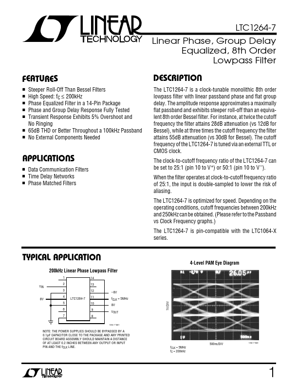
4-Level PAM Eye Diagram
14 13 12 11 10 9 8
1264-7 TA01
200k Hz Linear Phase Lowpass Filter
- 8V f CLK = 5MHz 8V VOUT
1V/DIV
NOTE: THE POWER SUPPLIES SHOULD BE BYPASSED BY A 0.1µF CAPACITOR CLOSE TO THE PACKAGE AND ANY PRINTED CIRCUIT BOARD ASSEMBLY SHOULD MAINTAIN A DISTANCE OF AT LEAST 0.2 INCHES BETWEEN ANY OUTPUT OR INPUT PIN AND THE f CLK LINE. f CLK = 5MHz f C = 200k Hz
500ns/DIV
1264-7 TA02
LTC1264-7 ABSOLUTE...