LTC1477
LTC1477 is Single and Dual Protected High Side Switches manufactured by Linear Technology.
LTC1477/LTC1478 Single and Dual Protected High Side Switches
Features s s s s s s s s s s s
DESCRIPTION
The LTC ®1477/LTC1478 protected high side switches provide extremely low RDS(ON) switching with built-in protection against short-circuit and thermal overload conditions. A built-in charge pump generates gate drive higher than the supply voltage to fully enhance the internal NMOS switch. This switch has no parasitic body diode and therefore no current flows through the switch when it is turned off and the output is forced above the input supply voltage. (DMOS switches have parasitic body diodes that bee forward biased under these conditions.) Two levels of protection are provided by the LTC1477/LTC1478. The first level of protection is shortcircuit current limit which is set at 2A. The short-circuit current can be reduced to as low as 0.85A by disconnecting portions of the power device (see Applications Information). The second level of protection is provided by thermal overload protection which limits the die temperature to approximately 130°C. The LTC1477 single is available in 8-lead SO packaging. The LTC1478 dual is available in 16-lead SO packaging.
, LTC and LT are registered trademarks of Linear Technology Corporation.
Extremely Low RDS(ON) Switch: 0.07Ω No Parasitic Body Diode Built-In Short-Circuit Protection: 2A Built-In Thermal Overload Protection Operates from 2.7V to 5.5V Inrush Current Limited Ultralow Standby Current: 0.01µA Built-In Charge Pump Controlled Rise and Fall Times: t R = 1ms Single Switch in 8-Pin SO Package Dual Switch in Narrow 16-Pin SO Package
U APPLICATIONS s s s s s s
Notebook puter Power Management Power Supply/Load Protection Supply/Battery Switch-Over Circuits Circuit Breaker Function "Hot Swap" Board Protection Peripheral Power Protection
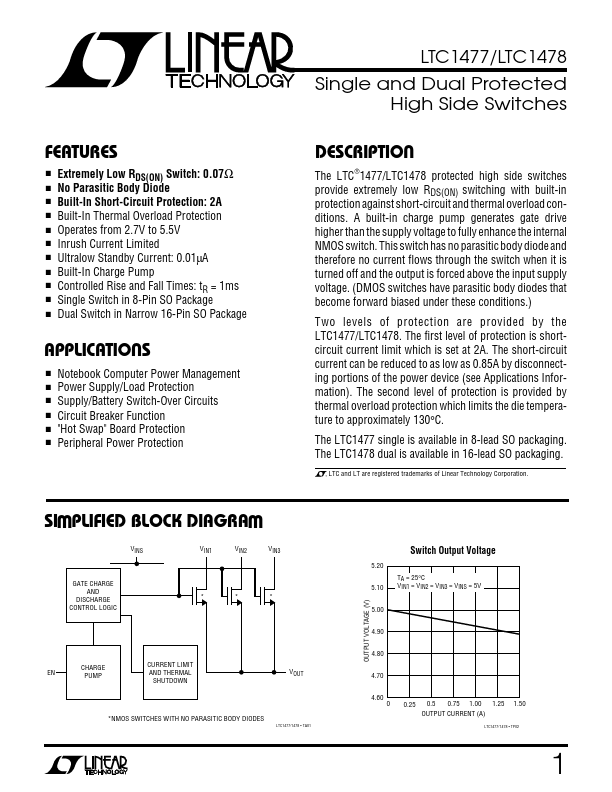
SI PLIFIED BLOCK DIAGRAM
VINS VIN1 VIN2
VIN3
OUTPUT VOLTAGE (V)
GATE CHARGE AND DISCHARGE CONTROL LOGIC
TA = 25°C VIN1 = VIN2 = VIN3 = VINS = 5V
- -
- 5.00 4.90...