DESCRIPTION
OF B SERIES CMOS DEVICES” DESCRIPTION
When a logic ”1” is present at the inhibit input terminal all channel are off. This device is a triple 2-channel multiplexer having three separate digital control inputs, A, B, and C, and an inhibit input. Each control input selects one of a pair of channels which are connected in a single pole double-throw configuration. 1/5 CC4053 INPUT EQUIVALENT CIRCUIT FUNCTIONAL DIAGRAM PIN DESCRIPTION
PIN No 11, 10, 9 6 12, 13, 2, 1, 5, 3 14 15 4 7 8 16 SYMBOL A, B, C INH IN/OUT OUT/IN OUT/IN OUT/IN VEE VSS VDD NAME AND FUNCTION Binary Control Inputs Inhibit Inputs ax,ay,bx,by,cx,cy Input/ Output ax or ay bx or by cx or cy Supply Voltage Negative Supply Voltage Positive Supply Voltage TRUTH TABLE INHIBIT C or B or A 0 0 1 X : Don’t Care 0 1 X ax or bx or cx ay or by or cy NONE 2/5 CC4053 ABSOLUTE MAXIMUM RATINGS
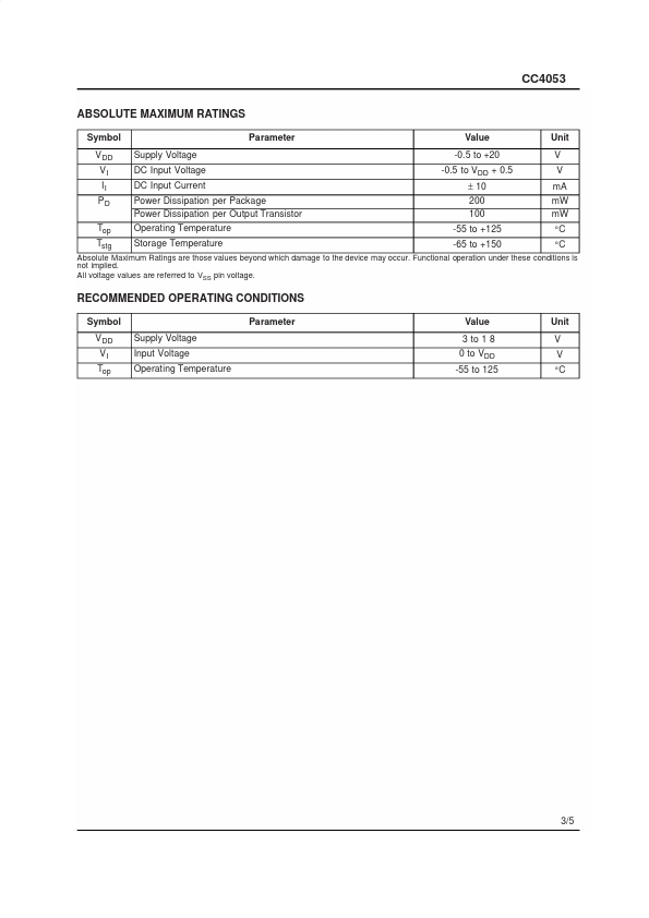
Symbol Parameter Value Unit VDD Supply Voltage -0.5 to +20 V VI DC Input Voltage -0.5 to VDD + 0.5 V II DC Input Current ± 10 mA PD Powe...