LTL2P3TBK5W
LTL2P3TBK5W is LED manufactured by LITEON.
- Part of the LTL2P3TBK5W_Lite comparator family.
- Part of the LTL2P3TBK5W_Lite comparator family.
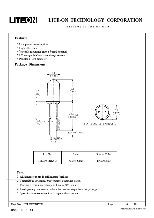
Features
- Low power consumption.
- High efficiency.
- Versatile mounting on p.c. board or panel.
- I.C. patible/low current requirement.
- Popular T-13/4 diameter.
Package Dimensions
Part No. LTL2P3TBK5W
Lens Water Clear
Source Color In Ga N Blue
Notes: 1. All dimensions are in millimeters (inches). .. 2. Tolerance is ±0.25mm(.010") unless otherwise noted. 3. Protruded resin under flange is 1.0mm(.04") max. 4. Lead spacing is measured where the leads emerge from the package. 5. Specifications are subject to change without notice.
Part No. : LTL2P3TBK5W BNS-OD-C131/A4
Page :
1 of
LITE-ON TECHNOLOGY CORPORATION
Property of Lite-On Only
Absolute Maximum Ratings at TA=25℃
Parameter Power Dissipation Peak Forward Current (1/10 Duty Cycle, 0.1ms Pulse Width) DC Forward Current Reverse Voltage Operating Temperature Range Storage Temperature Range Lead Soldering Temperature [1.6mm(.063") From Body] Maximum Rating 120 100 30 5 -25℃ to + 80℃ -30℃ to + 100℃ 260℃ for 5 Seconds Unit m W m A m A V
..
Part No. : LTL2P3TBK5W BNS-OD-C131/A4
Page :
2 of
LITE-ON TECHNOLOGY CORPORATION
Property of Lite-On Only
Electrical / Optical Characteristics at TA=25℃
Parameter Radiant Intensity Viewing Angle Peak Emission Wavelength Dominant Wavelength Spectral Line Half-Width Forward Voltage Reverse Current Symbol Ie 2θ1/2 λP λd ∆λ VF IR Min. 17.7 15 Typ. Max. 91.0 Unit m W/sr deg nm nm nm 3.8 100 V µA IF = 20m A VR = 5V Test Condition IF = 20m A Note 4 Note 1 (Fig.6) Measurement @Peak (Fig.1) Note 2
468 470 25 3.5
NOTE: 1. θ1/2 is the off-axis angle at which the luminous intensity is half the axial luminous intensity. 2. The dominant wavelength, λd is derived from the CIE chromaticity diagram and represents the single wavelength which defines the color of the device. 3. Ie classification code is marked on each packing bag. 4. The Ie guarantee should be added ±15% tolerance. 5. Precautions in handling: ‧ When soldering, leave 2mm of minimum clearance from the resin to the...