• Part: MP1403
  • Description: RTD Input Limit Alarm
  • Manufacturer: M-System
  • Size: 90.22 KB
Download MP1403 Datasheet PDF
M-System
MP1403
MP1403 is RTD Input Limit Alarm manufactured by M-System.
- Part of the MP1423_M comparator family.
INSTRUCTION MANUAL RTD INPUT LIMIT ALARM model MP1400 through MP1423 Thank you for choosing M-System. Before use, check specifications on the unit label. If you have any problems or questions with the product, please contact M-System’s Sales Office or representatives. General Description 
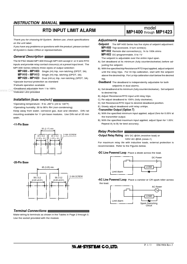
The M-PAC Model MP1400 through MP1423 accept 2- or 3-wire RTD inputs and provide relay contact closure(s) at a preset input level. The MP1400 Series reflects three styles of output selection: MP1400 - MP1403 Single (Hi) trip, non-latching (DPDT, 3A) MP1410 - MP1413 Single (Hi) trip, latching (DPDT, 3A) MP1420 - MP1423 Dual (Hi/Lo) trip, non-latching (SPDT, 3A) - Upscale burnout protection as standard - Failsafe operation available .Dat- - a DIn Sedaihcdaebtaoenrtd L4Ea UDdj.upcsrootavmbidleedfrom 1 to 100% Installation [Scale: mm(inch)] - Operating temperature: -5 to +60°C (23 to 140°F) - Operating humidity: 30 to 90% RH (non-condensing) Keep away from water, corrosive gas, dust and vibration. DIN rail mounting available for 11-pin-base modules. Use DIN rail of 35 mm width. - 11-Pin Base 55 (2.17) min. 40 ± 0.2 40 ± 0.2 2- M4 SCREW (1.57± .01) (1.57± .01) Adjustments - Setpoint The MP1400 Series has five styles of setpoint adjustment: MP14X0 Top-accessed, 3-turn screw(s) MP14X2 Remote dial connection(s), 1k to 100k ohms MP14X3 DC-programmable, 0 to 1V The setpoint is adjustable over the entire input span. A) Set deadband at its minimum (fully counterclockwise) before adjusting the setpoint. B) With the specified trip Resistance/RTD input applied, adjust setpoint until the relay trips. For Hi trip calibration, start with the setpoint above the desired trip. For Lo trip calibration start below the desired trip. - Deadband The deadband is independently adjustable for both setpoints in dual alarms. A) Set deadband at its minimum (fully counterclockwise). Set setpoint to desired trip. B) Adjust Resistance/RTD input until relay trips. C) Re-adjust deadband to 100% (fully clockwise). D)...