MADR-010574
MADR-010574 is 20V to 250V Driver for High Power PIN Diode Switches manufactured by MACOM Technology Solutions.
- Part of the MADR-010574-MA comparator family.
- Part of the MADR-010574-MA comparator family.
Features
- 20 V to 250 V Back Bias in Off State
- 200 m A Series Diode Bias Current at +25°C
- 50 m A Shunt Diode Bias Current at +25°C
- Propagation Delay less than 8 µs
- Low Quiescent Current Consumption
- 3 V or 5 V CMOS Logic Control
- 7 mm QFN-16LD Package
- Tape and Reel Packaging Available
- Ro HS- pliant and 260°C Reflow patible
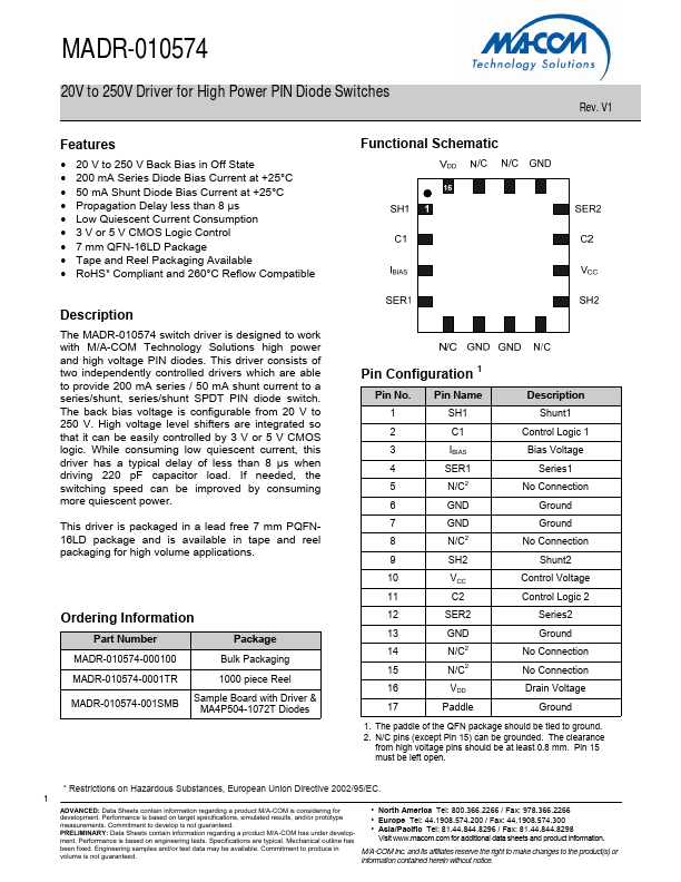
Functional Schematic
Rev. V1
Description
The MADR-010574 switch driver is designed to work with M/A- Technology Solutions high power and high voltage PIN diodes. This driver consists of two independently controlled drivers which are able to provide 200 m A series / 50 m A shunt current to a series/shunt, series/shunt SPDT PIN diode switch. The back bias voltage is configurable from 20 V to 250 V. High voltage level shifters are integrated so that it can be easily controlled by 3 V or 5 V CMOS logic. While consuming low quiescent current, this driver has a typical delay of less than 8 µs when driving 220 p F capacitor load. If needed, the switching speed can be improved by consuming more quiescent power.
This driver is packaged in a lead free 7 mm PQFN16LD package and is available in tape and reel packaging for high volume applications.
Ordering Information
Part Number
Package
MADR-010574-000100
Bulk Packaging
MADR-010574-0001TR
1000 piece Reel
MADR-010574-001SMB
Sample Board with Driver & MA4P504-1072T Diodes
Pin Configuration 1
Pin No. 1 2 3 4 5 6 7 8 9 10 11 12 13 14 15 16 17
Pin Name SH1 C1 IBIAS SER1 N/C2 GND GND N/C2 SH2 VCC C2 SER2 GND N/C2 N/C2 VDD
Paddle
Description
Shunt1
Control Logic 1 Bias Voltage Series1 No Connection Ground Ground No Connection Shunt2
Control Voltage Control Logic 2
Series2 Ground No Connection No Connection Drain Voltage Ground
1. The paddle of the QFN package should be tied to ground. 2. N/C pins (except Pin 15) can be grounded. The clearance from high voltage pins should be at least 0.8 mm. Pin 15 must be left open.
- Restrictions on Hazardous Substances, European Union...