MSK3013 Overview
Key Features
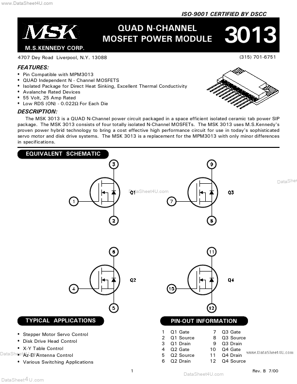
- Pin Compatible with MPM3013
- QUAD Independent N
- Channel MOSFETS
- Isolated Package for Direct Heat Sinking, Excellent Thermal Conductivity
- Avalanche Rated Devices
| Part | MSK3013 |
|---|---|
| Description | QUAD N-CHANNEL MOSFET POWER MODULE |
| Category | MOSFET |
| Manufacturer | MSK |
| Size | 346.04 KB |
| Part Number | Manufacturer | Description |
|---|---|---|
| HFDOM44P-xxxSx | Hanbit Electronics | 44Pin Flash Disk Module |
| HFDOM40B-xxxSx | Hanbit Electronics | 40Pin Flash Disk Module |
| HFDOM40P-xxxSx | Hanbit Electronics | 40Pin Flash Disk Module |