FEATURES
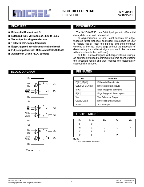
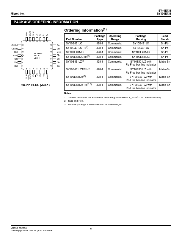
s Differential D, clock and Q s Extended 100E VEE range of –4.2V to –5.5V s VBB output for single-ended use s 1100MHz min. toggle frequency s Edge-triggered asynchronous set and reset s Fully compatible with Motorola MC10E/100E431 s Available in 28-pin PLCC package BLOCK DIAGRAM S0 D0 D0 CLK0 CLK0 R0 S1 D1 D1 CLK1 CLK1 R1 S2 D2 D2 CLK2 CLK2 R2 S DQ Q R S DQ Q R S DQ Q R VBB Q0 Q0 Q1 Q1 Q2 Q2 DESCRIPTION
The E431 is also designed with larger internal swings, an approach intended to minimize the time spent crossing the threshold region and thus reduces the metastability susceptibility window. PIN NAMES Pin D[0:2], D[0:2] CLK[0:2], CLK[0:2] S[0:2] R[0:2] VBB Q[0:2], Q[0:2] VCCO Function Differential Data Inputs Differential Clock Inputs Edge Triggered Set Inputs Edge Triggered Reset Inputs VBB Reference Output Differential Data Outputs VCC to Output TRUTH TABLE(1) Dn CLKn LZ HZ XL XL NOTE: 1. Z = LOW-to-HIGH transition. Rn L L Z L Sn L L L Z Qn L H L H M9999-032206 hbwhelp@micrel.com or (408) 955-1690 1 Rev.: E Amendment: /0 Issue Date: March 2006 Micrel, Inc. Micrel