GENERAL DESCRIPTION
The chips transmit circuit contain a 6 bit D/A converter to digitally modulate the IF, an anti alias filter and an image reject up-convert mixer. FEATURES
n Highly integrated IF transceiver n Data rates up to 4Mbps n Integrated discriminator and filter alignment circuits n High signal to noise ratio at the discriminator output n Received signal strength indicator (RSSI) n D/A Converter for digitally generated IF n Low sleep mode current - typically less than 1mA n 3.0V to 5.5V operation n Fast 10msec switch time between transmit and receive modes n 48 Pin TQFP, 7mm body APPLICATIONS
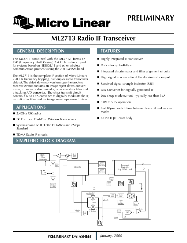
n 2.4GHz FSK radios n PC Card and FlashCard Wireless Transceivers n Systems based on IEEE802.11 1Mbps and 2Mbps Standard n TDMA Radio IF circuits SIMPLIFIED BLOCK DIAGRAM R. C. Loop Filter ML2731 Bias Controller Transmit Power Amplifier 2LO Loop Filter & Tank Circuit 3 ML2712 1LO Loop Filter & Tank Circuit Baseband Controller (e.g., MSM7730B) 6 Reference Frequency Input 32MHz Clock 2LO I... Micro Linear