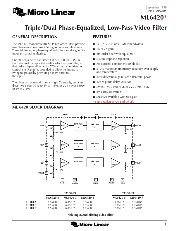
GENERAL DESCRIPTION
Cut-off frequencies are either 3.0, 5.5, 8.0, or 9.3MHz. A control pin (Range) is provided to allow the inputs to swing to ground by providing a 0.5V offset to the input. The filters are powered from a single 5V supply, and can drive 1VP-P over 75W (0.5V to 1.5V), or 2VP-P over 150W (0.5V to 2.5V). FEATURES
s s s s s s 3.0, 5.5, 8.0, or 9.3 MHz bandwidth 1X or 2X gain 6th-order filter with equalizer >40dB stopband rejection No external components or clocks ±10% maximum frequency accuracy over supply and temperature <2% differential gain, <2° differential phase <25ns group delay variation 5V ±10% operation ML6420 available with 6dB gain Drives 1VP-P into 75W, or 2VP-P into 150W s s s s s * Some Packages Are End Of Life ML 6420 BLOCK DIAGRAM VCCB 8 VCCC 6 VCC 5 VCCA 11 VINA 15 3k BUF LOW PASS A ALL PASS A 1X/2X BUF 3.33K 10 VOUTA IBIAS 1k VINB 16 3k BUF LOW PASS B ALL PASS B 1X/2X BUF 3.33K 9 VOUTB IBIAS 1k LOW PASS C IBIAS RANGE 14 1k 12 GND 13 GNDA 4 GNDC 1 GNDB 3 GND ALL PASS C VINC 2 3k BUF 1X/2X BUF 3.33K 7 VOUTC 1X GAIN ML6420-1 FILTER A FILTER B FILTER C 5.5MHZ 5.5MHZ 5.5MHZ 2X GAIN ML6420-4 8.0MHZ 3.0MHZ 3. Micro Linear