Microchip Technology AN597
The RE0 and RE1 I/O pins are configured as digital outputs and are tied to INIT and BINH, respectively. The CCP1 pin is configured as a digital input and is tied to ECHO through a pull-up resistor.| Part No. | AN597 |
|---|---|
| Datasheet | AN597 Download |
| Manufacturer |  Microchip Technology |
| Description | Implementing Ultrasonic Ranging |
| Buy | Stock & Price |
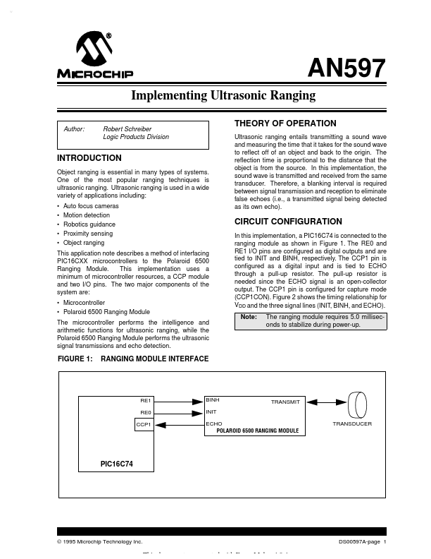
AN597 Implementing Ultrasonic Ranging Author: Robert Schreiber Logic Products Division THEORY OF OPERATION Ultrasonic ranging entails transmitting a sound wave and measuring the time that it takes for the sound wave to reflect off of an object and back to the origin. The reflection time is proportional to the distance that the object is from the source. In this implementation, the sound wave is transmitted and received from the same transducer. Therefore, a blanking interval is required between signal transmission and reception to eliminate false echoes (i.e., a transmitted signal being detected as its own echo). INTRODUCTION Object ranging is essential in many types of systems. One of the most popular ranging techniques is ultrasonic ranging. Ultrasonic ranging is used in a wide variety of applications including:
●
●
●
●
● Auto focus cameras Motion detection Robotics guidance Proximity sensing Object ranging CIRCUIT CONFIGURATION In this implementation, a PIC16C74 is connected to the ranging module as shown in Figure 1.
●
●
●
●
● Auto focus cameras Motion detection Robotics guidance Proximity sensing Object ranging CIRCUIT CONFIGURATION In this implementation, a PIC16C74 is connected to the ranging module as shown in Figure 1.