Microchip Technology MCP19125
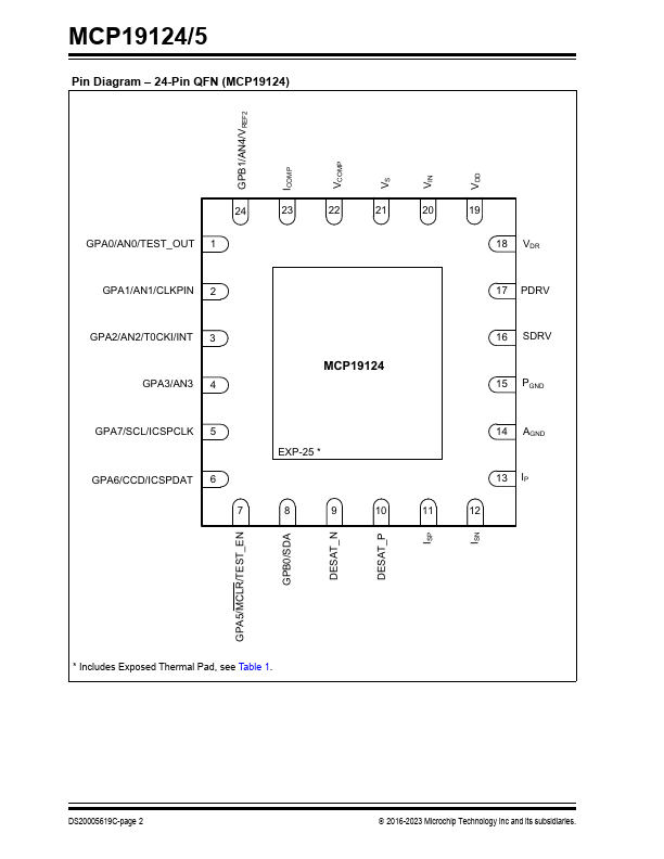
The Analog/Digital Debug Output is selected through the control of the ABECON register. The IOC is disabled when MCLR is enabled.| Part No. | MCP19125 |
|---|---|
| Datasheet | MCP19125 Download |
| Manufacturer |  Microchip Technology |
| Description | Low-Side Dual-Loop PWM Controller |
| Buy | Stock & Price |
FEATURES
● AEC-Q100 Automotive Qualified, See Section “Product Identification System”● Input Voltage: 4.5V to 42V
● Individual Analog Control Loops for Current or Voltage Regulation
● Can be configured with multiple topologies including but not limited to: - Flyback - Ćuk - Boost - SEPIC (Single-Ended Primary-Inductor Converter)
● Capable of Quasi-Resonant or Fixed-Frequency Operation
● Low Quiescent Current: 5 mA Typical
● Low Sleep Current: 50 µA Typical
● Low-Side Gate Drivers: - +5V gate drive with 0.5A sink/source current - +10V gate drive with 1A sink/source current
● Peak Current Mode Control
● Differential Remote Output Sense
● Multiple Output Systems: - Master or Slave
● AEC-Q100 Qualified
● Configurable Parameters: - VREF, Precision IOUT/VOUT Set Point (DAC) - ADC Reference Switch (VDD or AVDD) - Input Undervoltage Lockout (UVLO) - Input Overvoltage Lockout (OVLO) - Detection and protection - Primary current leading edge blanking (0 ns, 50 ns, 100 ns and 200 ns) - Gate drive...