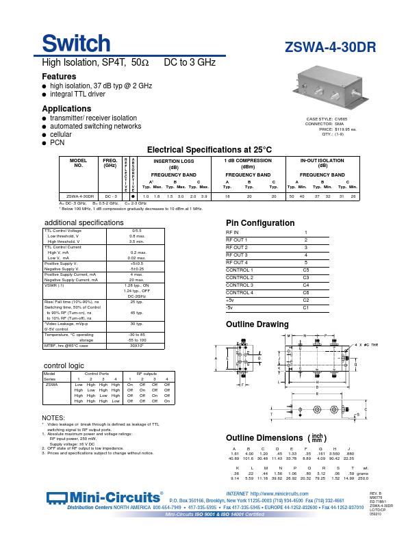
ZSWA-4-30DR
ZSWA-4-30DR is Switch High Isolation/ SP4T/ 50 DC to 3 GHz manufactured by Mini-Circuits.
- Part of the ZSWA-4-30DR_Mini comparator family.
- Part of the ZSWA-4-30DR_Mini comparator family.
Features l l
DC to 3 GHz high isolation, 37 d B typ @ 2 GHz integral TTL driver
Applications l l l l transmitter/ receiver isolation automated switching networks cellular PCN
MODEL NO. FREQ. (GHz)
R E F L E C T I V E A B S O R P T I V E
CASE STYLE: CONNECTOR: PRICE: QTY.:
CV665 SMA $119.95 ea. (1-9)
Electrical Specifications at 25°C
INSERTION LOSS (d B) FREQUENCY BAND
A† B C Typ. Max. Typ. Max. Typ. Max. 1.0 1.8 1.5 3.0 2.0 3.9
1 d B PRESSION (d Bm) FREQUENCY BAND
A Typ. 18 B Typ. 20 C Typ. 20
IN-OUT ISOLATION (d B) FREQUENCY BAND
A Typ. Min. 50 40 B Typ. Min. 37 32 C Typ. Min. 31 26
- 3 l
A= DC-.5 GHz, B= 0.5-2 GHz, C= 2-3 GHz † Below 100 MHz, 1 d B pression gradually decreases to 10 d Bm at 1 MHz. additional specifications
TTL Control Voltage Low threshold, V High threshold, V TTL Control Current High V, m A Low V, m A Positive Supply V. Negative Supply V. Positive Supply Current, m A Negative Supply Current, m A VSWR (:1) 0/5.5 0.8 max. 3.5 min. 0.2 max. 0.02 max. +5±0.5 -5±0.25 4 max. 20 max. 1.28 typ., ON 1.24 typ., OFF DC-2GHz 25 typ. 45 typ. 30 typ. -30 to 85 -55 to 100 30X106
Pin Configuration
RF IN RF OUT 1 RF OUT 2 RF OUT 3 RF OUT 4 CONTROL 1 CONTROL 2 CONTROL 3 CONTROL 4 +5v -5v 1 2 3 4 5 C5 C3 C4 C6 C2 C1
Rise/ Fall time (10%-90%), ns Switching time, 50% of Control to 90% RF (Turn-on), ns to 10% RF (Turn-off), ns
- Video Leakage, m Vp-p 0/-5V control Temperature, °C operating storage MTBF, hrs @85°C case
Outline Drawing control logic
Model Series ZSWA Control Ports 1 2 3 4 Low High High High High Low High High High High Low High High High High Low 1 On Off Off Off RF outputs 2 3 Off Off On Off Off On Off Off 4 Off Off Off On
NOTES:
- Video leakage or break through is defined as leakage of TTL switching signal to RF output ports. 1. Absolute maximum power and voltage ratings: RF input power, 250 m W, Supply voltage: ±6 V DC 2. OFF state of RF output is low impedance. 3. Prices and specifications subject to change without...