MH89792
MH89792 is E1 Transceiver manufactured by Mitel Networks.
Features
- -
- -
- -
- -
- plete primary rate 2048kb/s CEPT line driver and receiver Onboard pulse transformers for transmit and receive Meets latest ETSI requirements (ETSI ETS 300 011 (NET 5)) Inductorless clock recovery Loss of signal indication/ polarity selection Programmable polarity of extracted clock & receive data Single +5V operation patible with all E1 framers Small footprint area (<330mm 2)
MH89792-1 MH89792-2 MH89792-3
ISSUE 3
April 1995
Ordering Information
20 Pin SIL Package 20 Pin SIL Package 20 Pin SIL Package
0° C to 70° C
Description
The Mitel MH89792 is a low cost E1 line driver/ receiver with clock extraction requiring no external ponents. There are three versions available: MH89792-1 for 120Ω twisted pair cable; MH89792-2 for 75Ω co-axial links; MH89792-3 for 100Ω digital twisted pair.
Applications
- -
- - Primary rate ISDN network Interface Multiplexer equipment Private Network links Isochronous LANS/WANS
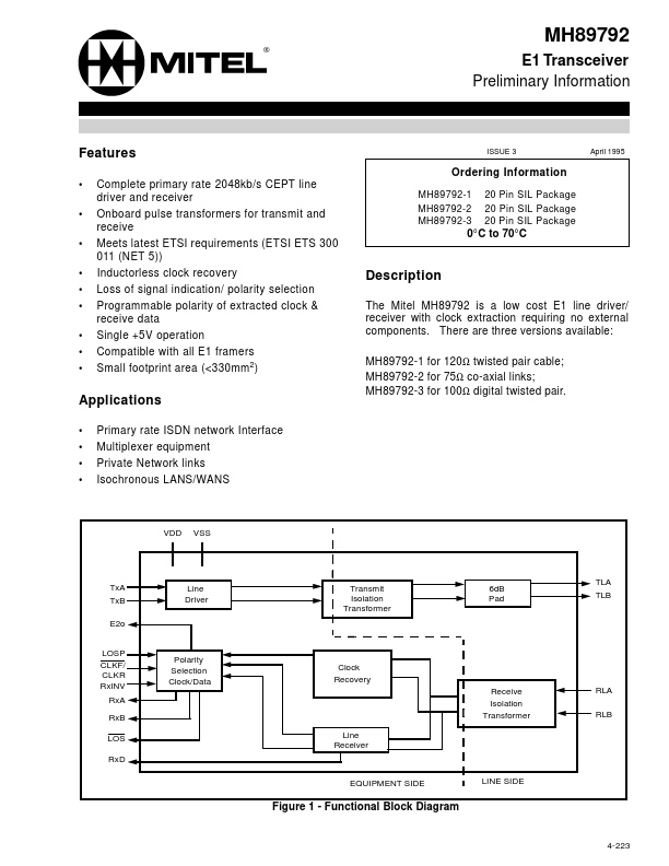
Tx A Tx B E2o LOSP CLKF/ CLKR Rx INV Rx A Rx B LOS Rx D
Line Driver
Transmit Isolation Transformer
6d B Pad
TLA TLB
Polarity Selection Clock/Data
Clock Recovery Receive Isolation Transformer Line Receiver RLA RLB
EQUIPMENT SIDE
LINE SIDE
Figure 1
- Functional Block Diagram
4-223
E2o VDD Rx A Rx B VSS Rx D Rx INV CLKF/CLKR LOS LOSP NC RLA RLB TLA TLB NC NC NC Tx A Tx B 1 2 3 4 5 6 7 8 9 10 11 12 13 14 15 16 17 18 19 20
Preliminary Information
Figure 2
- Pin Connections
Pin Description
Pin # 1 2 3 Name E2o VDD Rx A Description
2048k Hz Extracted clock (Output). This clock is extracted by the device from the received signal. It is used internally to clock in data received from RLA and RLB. D.C. Power (Input) +5V supply Receiver A (Output). The bipolar CEPT signal received by the device at RLA and RLB inputs is converted to a unipolar format and output at this pin. This pin should be connected to the positive receive pin of the framer. Receiver A (Output). This pin should be connected to the negative receive gain pin of...