M62256FP
M62256FP is Single chip battery charger control IC manufactured by Mitsubishi Electric.
Mitsubishi Integrated Circuit <Digital/Analog Interface>
Single chip battery charger control IC Outline
M62256FP is a semiconductor integrated circuit designed to control the battery charger. This IC controls not only all the time sequence needed for battery charging,but also gives full support for detection of battery temperature,protection over current and voltage,and safety timer,etc. It is also a simple matter to charge Ni-Cd,Ni-MH batteries by adding a small peripheral ponents to this IC. This IC has a feedback controlling of the charge current and the output voltage.
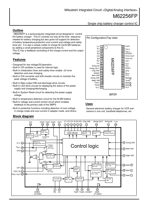
Pin Configuration(Top view)
1 2 3 4 5 6 7 8 9 10 11 12 13 14 15 16 17 18 36 35 34 33 32 31 30 29 28 27 26 25 24 23 22 21 20 19 Vref1
Features
- Designed for low voltage(3V)operation.
- Built-in CR oscillator is used for internal logic.
- Built-in initialization timer and safety timer enable -∆V error detection and over-charging.
- Built-in D/A converter and shift-resister circuits to maintain the peak voltage of battery.
- Built-in Main output SW and discharge drive circuits.
- Built-in LED drive circuits for displaying the status of the power supply and charging/discharging.
- Built-in System Reset circuit for detecting the power supply voltage.
- Built-in temperature detection circuit for the Ni-MH battery
- Built-in voltage and current control circuit which enables feedback to the primary side of the SMPS.
- Built-in protective functions including detection of over-voltage in charge mode and over-current in adapter mode, and others.
C1 E1 C2 E2 C3 E3 Rc Cc Dchg IN Dchg OUT Chg SW GND2 Batt SW Dchg SW Adpt SW Test1 Test2 N.C
OCSET PCS OUT PCS IN CP1
I SET2 I SET1
36P2R
I DET
Vcc GND1 CP2
VDET
P.C Batt T Vref2 Batt Batt + N.C
Uses
General electronic battery charger for VCR and camera in one unit, handheld telephones, etc.
Block diagram
Vcc
Vref2 Vref1 Iset2
22 36...