MR-J3
Key Features
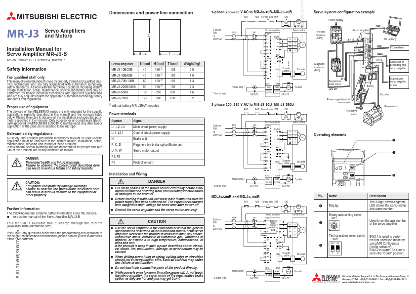
- Source logic
- Source logic
| Part Number | Manufacturer | Description |
|---|---|---|
| 2SK1818-MR | Fuji Electric | N-Channel MOSFET |
| MT6325 | MagnTek | MR Switch Sensor |
| K903 | Fuji Electric | 2SK903-MR |
| K949-MR | Fuji Electric | 2SK949-MR |
| 2SK1096-MR | Fuji Electric | N-CHANNEL SILICON POWER MOSFET |
| MR-224 | Synergy | THROUGH-HOLE 8 PIN-RELAY CAN |
| TDA5155 | NXP Semiconductors | Pre-amplifier for Hard Disk Drive HDD with MR-read/inductive write heads |
| TDA5360 | NXP Semiconductors | Pre-Amplifier for Hard Disk Drive with MR-Read / Inductive Write Heads |
| MR-6A | Mosdesign | RC CAR 7 FUNCTIONS |
| MRX1518HXA | AnaSem | CMOS MR MAGNETIC SENSOR SWITCH |