MSM9026
MSM9026 is Emulation Board for S1207 manufactured by Mosel Vitelic.
Features
To emulate S1207 chip and its derivatives, see data sheet PID 247. Driven by either 1.5 V x 4 battery or 5
- 6 V power supply. A 4x1 jumper header JP1 is provided to accept power source. A pair or strengthen wire (E1 & E2) is provided to accept the power source. 2 push button switches are provided to control the power on/off. Selectable (by JP2) auto power off function (after 60" no operation)is provided. A push button switch is provided to reset this M9026 board.
Emulation Board for S1207
A red LED lamp D3 is provided to indicate the power on or off. A 32-pin textool U3 is provided to store 27C010 EPROM (access time 120 ns or faster). 5 green LED lamps are provided on EAC area. 5 red LED lamps are provided on EAC area. 19 push button switches for triggers are provided on EAC area. A 2x1 jumper header JP4 is provided on EAC area to accept wires to speaker. A 3x1 jumper header JP5 is provided on EAC area to decide source for K1,2,3,4 triggers. A 3x5 jumper header is provided on EAC area to select LED lamps for 5 output pins or not. To be continued on page 3/6.
Description
By storing digitized sound data and options into 27C010 and inserting it onto U3, this MSM9026 board emulates the function of S1207 chip and its derivatives. The file for 27C010 content should be prepared by running program 9026pack.exe. The demanded external ponents are provided on board in specific EAC (External Application ponent) area.
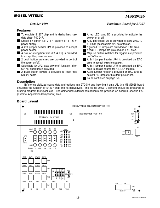
Board Layout
MOSEL VITELIC INC., MSM9026 V1M1 1996
E1 Vcc
U3
U2
(80C31) 9026 F/W 1.00
TEXTOOL for 27010
1.5V x4 JP1 E2 GND
(Red) OS DRV JP4
Vdd TGA TGB TGC OS OW OX OY OZ
SW JP3
Vss K1 K2 K3 K4 RW1 RW2 RW3 RW4 Cout
JP2 Auto Power Off RST
SPK SNK (Green) OS SN: OW OX OY OZ
SW4
SW8
SW12
SW16 RW4
SW3
SW7
SW11
SW15 RW3 HI A B C Vdd SEL RW2 LO A B C OKY RW1 JP5
SW2
SW6
SW10
SW14
RW1 INT SW...